

Centrosymmetric radial bipolar plate flow field structure for solid polymer electrolyte (SPE) electrolysis
A centrosymmetric, bipolar plate technology, applied in the direction of electrodes, electrolysis process, electrolysis components, etc., can solve the problems of unfavorable large flow SPE single stack development, reduce the service life of the stack, and the gas cannot be discharged in time, so as to improve the contact Insufficient and diversion, reducing mass transfer resistance, improving electrolysis efficiency and service life
- Summary
- Abstract
- Description
- Claims
- Application Information
AI Technical Summary
Problems solved by technology
Method used
Image

Examples
Embodiment
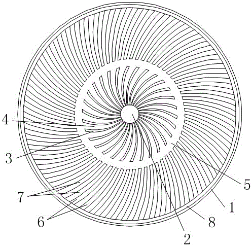
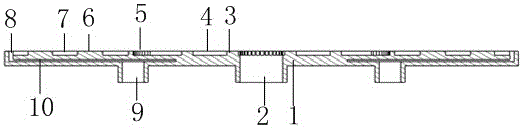
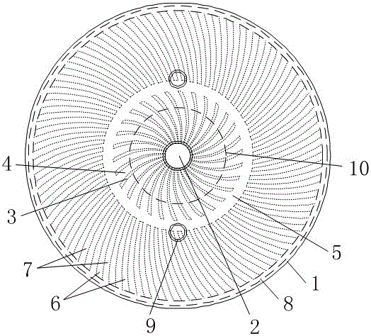
[0031] Such as Figure 1 to Figure 3 As shown, the center-symmetrical radial bipolar plate flow field structure is mainly used for SPE electrolysis, including a circular or regular polygonal bipolar plate body 1, an inlet nozzle 2 and an outlet arranged on the bipolar plate body 9. The feed nozzle is located at the center of the bipolar plate body, that is, the centroid of a circle or a regular polygon. The front of the bipolar plate body is sequentially arranged as the feed nozzle, the inner ring ridge 3, the pressure equalization transition zone 5, the outer ring ridge 6, the water outlet groove 8, and the outer edge of the bipolar plate body from inside to outside.
[0032] There are multiple inner ring ridges, which are symmetrically distributed on the body of the bipolar plate with the feeding nozzle as the center, thereby forming an inner radial flow channel 4 with a corresponding number of flow channel units, one end of which is connected to the The feed nozzle, the ot...
PUM
 Abstract
Description
Claims
Application Information