
Integrated testing device and method for compression rigidity and bending rigidity of metal bipolar plate

A metal bipolar plate, bending stiffness technology, applied in the direction of measuring device, using stable bending force to test material strength, using stable tension/pressure to test material strength, etc., can solve the problem of inability to test the stiffness of metal bipolar plate , the compressive stiffness and bending stiffness were not retrieved, and the maximum pressure value of the component could not be recorded, etc.

Inactive Publication Date: 2016-08-10
CHINA UNIV OF PETROLEUM (EAST CHINA)
View PDF9 Cites 5 Cited by
  • Summary
  • Abstract
  • Description
  • Claims
  • Application Information

AI Technical Summary

Problems solved by technology

[0005] After retrieving domestic and foreign patent documents, the State Intellectual Property Office of China published the publication number CN204882241U on December 16, 2015, and the name is "A Stiffness Testing Device and System". This invention mainly tests the components through the test bracket. Although the method is simple and feasible, the device uses an indenter, which cannot test the stiffness of the whole part of the component such as the metal bipolar plate.
The State Intellectual Property Office of China published the publication number CN203672706U on June 25, 2014, and the name is "a bending strength testing device". This utility model provides a bending strength testing device, which can ensure The stability of the sample, but the device cannot record the maximum pressure that the member can withstand when it bends
In addition, there is no patent literature that can meet the requirements of measuring the compressive stiffness and bending stiffness of components at the same time.

Method used


Image

  • Integrated testing device and method for compression rigidity and bending rigidity of metal bipolar plate
  • Integrated testing device and method for compression rigidity and bending rigidity of metal bipolar plate
  • Integrated testing device and method for compression rigidity and bending rigidity of metal bipolar plate

Examples


Embodiment Construction

[0036] The specific implementation process of the present invention will be further described in conjunction with the accompanying drawings.

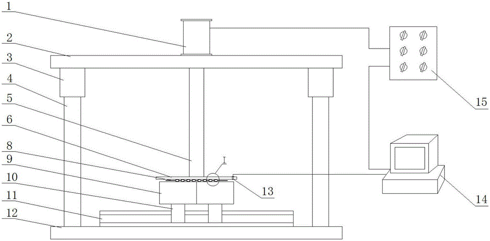
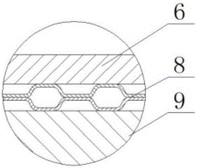
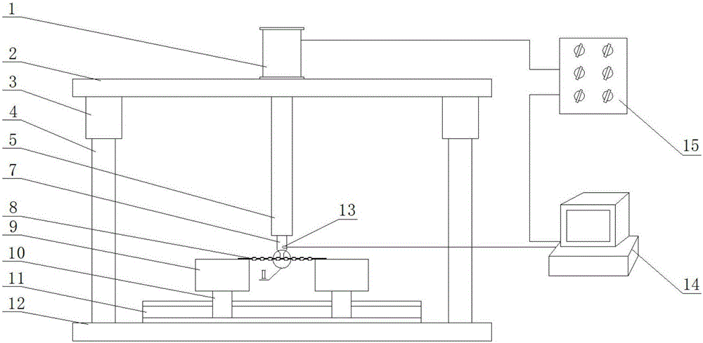
[0037] Such as figure 1 , figure 2 , image 3 , Figure 4 , Figure 5 As shown, a metal bipolar plate compression and bending rigidity integrated test device consists of a hydraulic system 1, a support plate 2, a guide sleeve 3, a guide post 4, a dowel bar 5, a pressure plate 6, a pressure head 7, a metal Bipolar plate 8, support platform 9, slide block 10, slide rail 11, workbench 12, displacement sensor 13, data processing system 14 and hydraulic control system 15 constitute.

[0038] The workbench 12 and the support plate 2 are rectangular rigid bodies correspondingly matched, and a guide column 4 is respectively fixed on the left and right sides of the workbench 12, and the guide sleeve 3 is fixed at the position corresponding to the guide column 4 fixed on the support plate 2 and the workbench 12; The sleeve 3 is equipped wit...


PUM


Abstract

The invention relates to an integrated test device and method for compressive and bending rigidity of a metal bipolar plate. The device consists of hydraulic system, support plate, guide sleeve, guide column, dowel rod, pressure plate, pressure head, metal bipolar plate, support table, slider, slide rail, workbench, displacement sensor, data processing system and hydraulic control System Components. The test method is to press the metal bipolar plate by gradually increasing the pressure of the pressure plate or the pressure head through the hydraulic control system, and observe the displacement-pressure image in the data processing system. The pressure corresponding to the inflection point in the image is the metal bipolar plate. withstand extreme loads. The present invention provides a feasible and effective testing device and method for testing the compressive and bending stiffness of metal bipolar plates, which can predict in advance the ultimate load that the metal bipolar plates can withstand, thereby preventing the metal bipolar plates from being subjected to The loss caused by excessive load deformation failure.

Description

1. Technical field [0001] The invention relates to a thin-plate ultimate load testing technology, in particular to an integrated testing device and method for compressive and bending rigidity of a metal bipolar plate. 2. Background technology [0002] A proton exchange membrane fuel cell (PEMFC) is a device that efficiently converts chemical energy into electrical energy, and its main fuels are oxygen and hydrogen. PEMFC has outstanding features such as high energy conversion efficiency, environmental friendliness, quick startup at room temperature, no electrolyte loss, easy water discharge, long life, high specific power and specific energy, and is therefore considered to be the most powerful competitor to replace traditional energy sources. The main factor hindering the commercial application of PEMFC is the high cost. As the main component of PEMFC, the bipolar plate accounts for 30%-45% of the cost of PEMFC. In order to reduce the production cost of fuel cells, and due...

Claims


Application Information

Patent Timeline
Patent Type & Authority Applications(China)
IPC IPC(8): G01N3/10G01N3/20
CPCG01N3/10G01N3/20G01N2203/0019G01N2203/0023G01N2203/0048G01N2203/0282
Inventor 徐书根王冲蒋文春韦洋
Owner CHINA UNIV OF PETROLEUM (EAST CHINA)
Learn More