
Spinning tool and metal surface spinning strengthening method

A technology for spinning tools and metal surfaces, applied in the field of spinning tools and metal surface spinning strengthening, can solve the problem of unsatisfactory surface strengthening effect of high-strength metal materials, poor surface metal grain refinement effect, and rough surface of metal components, etc. problem, to achieve the effect of being conducive to promotion, improving bending fatigue life, and simple implementation

Active Publication Date: 2018-03-06
INST OF METAL RESEARCH - CHINESE ACAD OF SCI
View PDF9 Cites 0 Cited by
  • Summary
  • Abstract
  • Description
  • Claims
  • Application Information

AI Technical Summary

Problems solved by technology

From the perspective of surface integrity, although the mechanical properties of components are improved, the impact on the surface geometry of components will lead to surface roughness, resulting in a decrease in its anti-fatigue effect. This is the weakness of shot peening technology
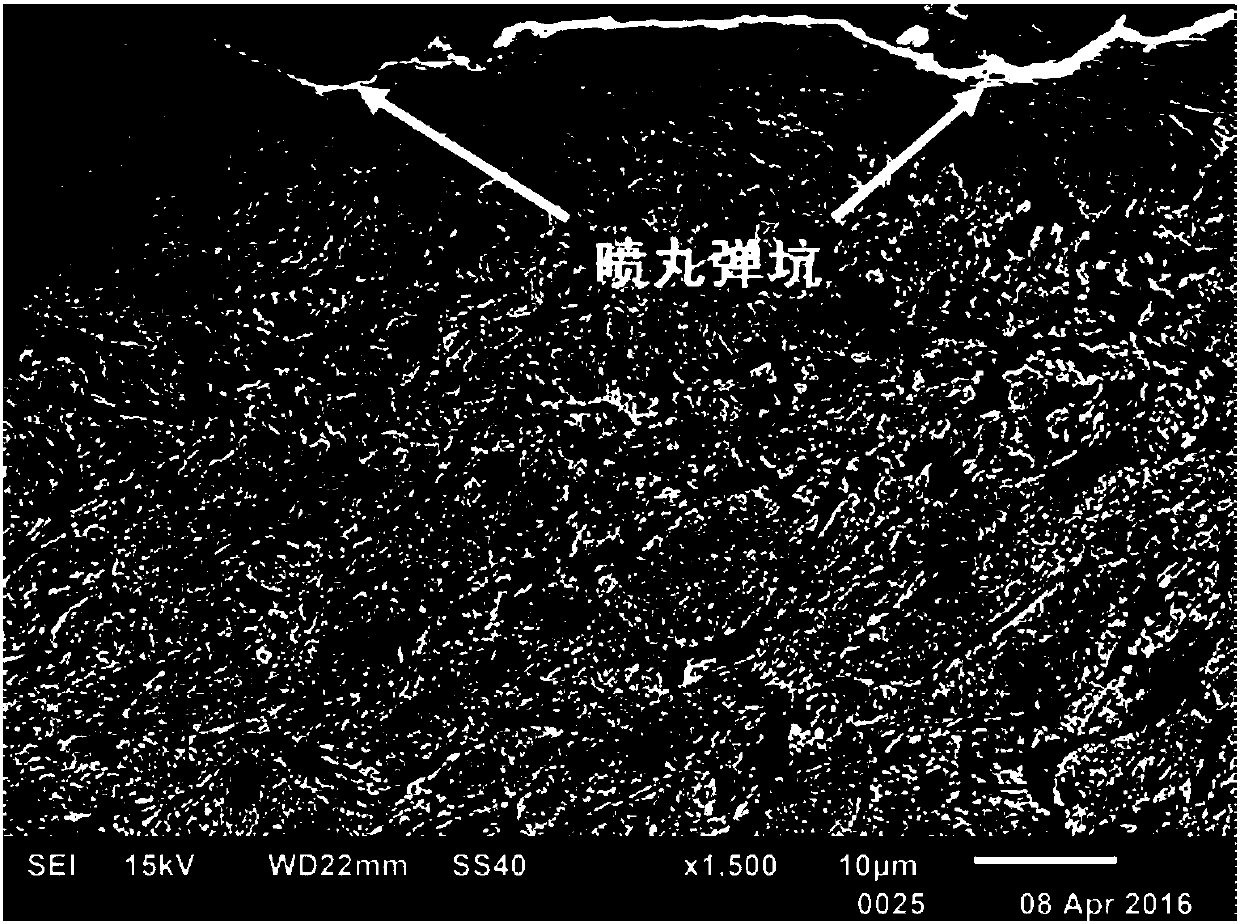
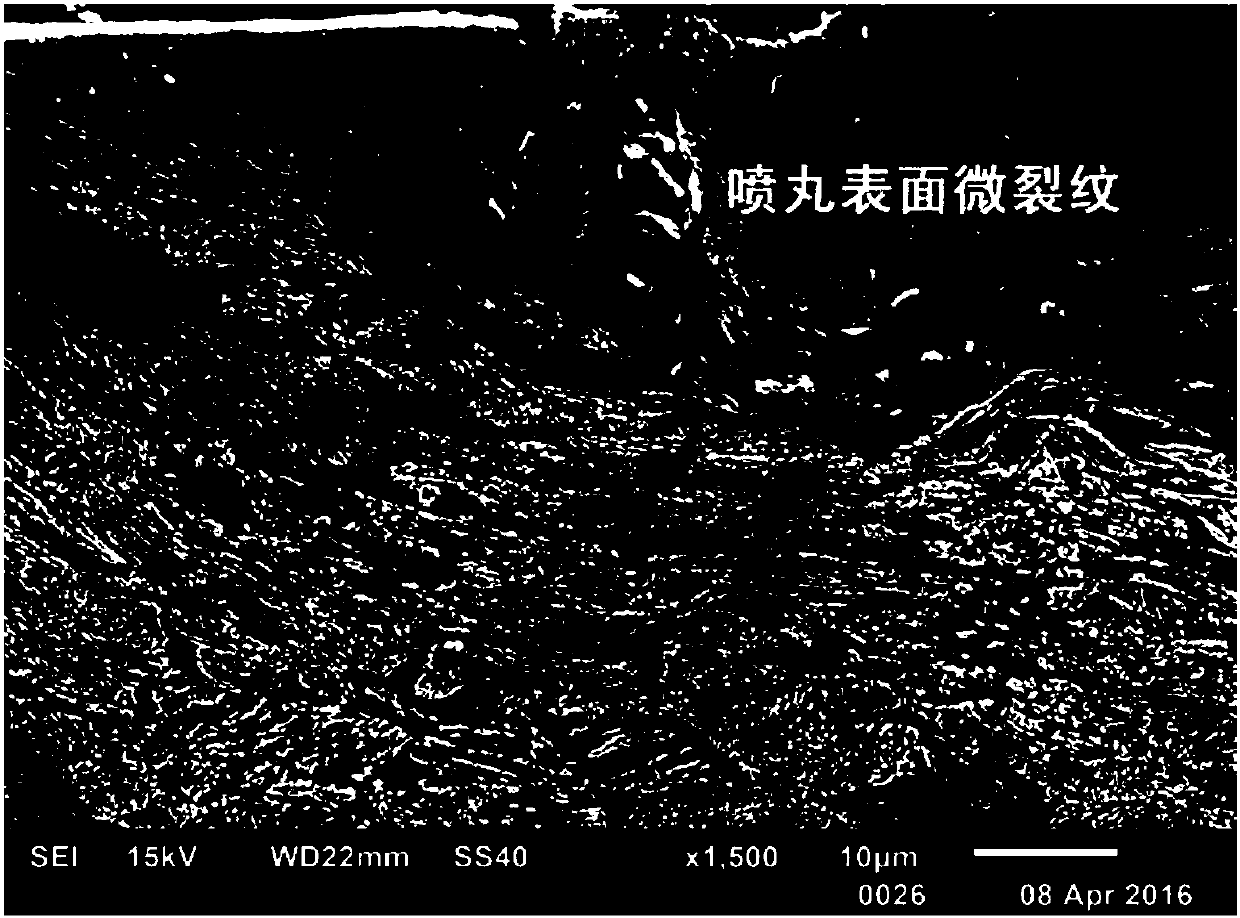
[0009] Third, during shot peening, individual projectiles with higher energy are likely to cause microcracks on the surface of components
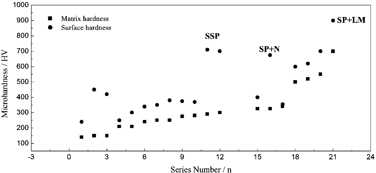
[0010] Fourth, the surface strengthening effect is poor when shot peening is used to treat high-strength metal materials
Its disadvantage is that the surface of the metal component is rough after shot peening, and the grain refinement effect of the surface layer metal is slightly poor. Individual high-energy projectiles hit the processed metal surface and are prone to random surface micro-cracks, especially for surface strengthening of high-strength metal materials. Unsatisfactory effect

Method used


Image

  • Spinning tool and metal surface spinning strengthening method
  • Spinning tool and metal surface spinning strengthening method
  • Spinning tool and metal surface spinning strengthening method

Examples


Embodiment 1

[0061] A spinning tool, such as Figure 4 As shown, the cutter adopts a cylindrical structure, the cutter head adopts an arc surface geometric structure, the radius of curvature of the arc surface is 2mm, and four openings are arranged on the cutter head, as Figure 5 As shown, the opening positions are evenly distributed along the circumferential direction. The role of setting the opening is to throw away a small amount of metal fines generated by wear from the center of the tool, and at the same time accelerate the cooling of the tool, reducing the damage to the tool caused by a small amount of metal chips and the temperature generated by processing.

[0062] The material of the spinning tool is W18Cr4V high-speed tool steel, and the metal matrix to be processed is 60Si2Mn spring steel with an average microhardness of 480HV and a tensile strength of 1600MPa.

[0063] Using the above-mentioned spinning tool, the method of spinning and strengthening the surface of 60Si2Mn spr...

Embodiment 2

[0071] A spinning cutter, same as embodiment 1.

[0072] Using the above-mentioned spinning tool, the method of spinning and strengthening the surface of 60Si2Mn spring steel is as follows:

[0073] Step 1: Remove the oil stain and rust layer on the surface of the 60Si2Mn spring steel by sandblasting;

[0074] Step 2: Make the spinning tool contact with the surface of 60Si2Mn spring steel, and the axis of the spinning tool is perpendicular to the surface of the processed 60Si2Mn spring steel;

[0075] Step 3: Use a milling machine to rotate the spinning tool quickly, and the tool rotates relative to the 60Si2Mn spring steel to apply shear stress to the surface of the 60Si2Mn spring steel, that is, to introduce residual compressive stress, to achieve grain refinement on the surface layer, and to achieve work hardening. Gradient microstructure, stop the operation when the processing area is reached; among them, the pressing amount of the spinning tool is 200 μm, the feeding speed...

Embodiment 3

[0082] A spinning tool, such as Figure 6 As shown, the tool adopts a cylindrical structure, and four metal hemispheres are arranged on the bottom surface of the cylinder of the spinning tool. The diameter of the metal hemispheres is 3 mm, and the positions of the metal hemispheres are evenly distributed along the circumferential direction. A plurality of metal hemispheres are evenly distributed on the plane, and the metal hemispheres are used to introduce residual compressive stress to the surface of the processed metal component and realize grain refinement.

[0083] The hardness of the spinning tool is higher than the initial surface hardness of the metal component to be processed.

[0084] The material of the spinning tool is a ceramic material, and the metal matrix to be processed is 30CrNi2.5MoV steel with an average microhardness of 330HV and a tensile strength of 1000MPa.

[0085] Using the above-mentioned spinning tool, the method of spinning and strengthening the su...


PUM

PropertyMeasurementUnit
depthaaaaaaaaaa
microhardnessaaaaaaaaaa
tensile strengthaaaaaaaaaa

Abstract

The invention discloses a rotary pressing tool and a rotary pressing strengthening method of a metal surface and belongs to the technical field of metal surface strengthening methods. A columnar structure is adopted for the rotary pressing tool. An arc-face structure is adopted for a tool bit. The tool bit is provided with 1-30 openings; or one or more metal semi-spheres are arranged on the bottom face of the columnar structure of the rotary pressing tool. The rotary pressing strengthening method of the metal surface includes the steps that firstly, oil dirt and corrosion products on the metal surface are removed; secondly, the rotary pressing tool makes contact with the metal surface, and the axis of the rotary pressing tool is perpendicular to the metal surface; and thirdly, the rotary pressing tool rotates at high speed, the metal surface passes through the position below the tool, the tool performs rotary pressing movement relative to a metal workpiece, and operation is stopped when a treatment area is achieved. The method is suitable for various metal materials and alloys thereof, such as low-strength steel and high-strength steel, the strength and hardness of the metal surface can be improved, a gradient structure is obtained, and the fatigue service life is prolonged; and meanwhile, implementation is easy, the process is not complicated, popularization is facilitated, and energy conservation and emission reduction can be achieved easily.

Description

technical field [0001] The invention belongs to the technical field of metal surface strengthening methods, in particular to a spinning tool and a metal surface spinning strengthening method. Background technique [0002] Through investigation and statistical analysis, it is found that fatigue fracture is the main cause of failure of metal components, accounting for more than 60% of the total number of failure cases of metal components. Fatigue fracture of metal components during service will bring huge economic losses to society every year , Sometimes even cause casualties, so its harm is very great. From a definition point of view, fatigue fracture refers to a failure phenomenon that a metal component undergoes fracture damage after a long period of service under alternating load or cyclic load. [0003] The fatigue cracking process of metal components can be divided into two main stages: the crack initiation stage and the crack growth stage. For most metal components se...

Claims


Application Information

Patent Timeline
Patent Type & Authority Patents(China)
IPC IPC(8): C21D7/04C22F1/08
CPCC21D7/04C22F1/08
Inventor 张哲峰王强朱艳坤
Owner INST OF METAL RESEARCH - CHINESE ACAD OF SCI
Learn More