
Vibration diaphragm of sound production device

A sounding device and the same technology, applied in the direction of diaphragm extension, planar diaphragm, diaphragm structure, etc., can solve the problems of power resistance, poor voltage, change of diaphragm properties, excessive amplitude, etc., and achieve good high temperature resistance , good acoustic performance, good sound quality effect

Active Publication Date: 2016-08-17
GOERTEK INC
View PDF4 Cites 11 Cited by
  • Summary
  • Abstract
  • Description
  • Claims
  • Application Information

AI Technical Summary

Problems solved by technology

Traditional loudspeaker diaphragms are mostly composite diaphragms. However, some limitations of the process structure of these composite diaphragms make the sound quality of the speakers unsatisfactory.
[0003] Traditional composite diaphragms usually use adhesive films to achieve the bonding between multi-layer films. The structural characteristics of acrylic adhesive films determine that the loudspeaker diaphragms that use them will inevitably have the following two defects: first , poor heat resistance
Under high-temperature molding conditions, the physical properties of the acrylic film will change due to excessive temperature, resulting in problems such as poor molding state of the diaphragm or changes in the properties of the diaphragm; second, poor power resistance and voltage resistance
As the power and voltage test requirements of the speaker are getting higher and higher, the voice coil transmits higher heat when it vibrates, and the properties of the traditional acrylic film are easily changed, which will cause the resonance frequency of the diaphragm to change, the amplitude is too large, and the distortion increases. Problems such as poor hearing
In the prior art, although the rigidity of the diaphragm can be enhanced through some designs, and the temperature of the environment can be reduced through product structure design, etc., the above methods have their limitations.

Method used


Image

  • Vibration diaphragm of sound production device
  • Vibration diaphragm of sound production device
  • Vibration diaphragm of sound production device

Examples


Embodiment 1

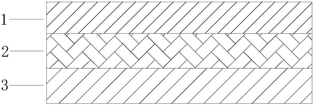
[0027] refer to figure 1 , the present invention provides a vibrating membrane of a sounding device, which includes a first engineering plastic layer 1, a second engineering plastic layer 3, and an adhesive film layer between the first engineering plastic layer 1 and the second engineering plastic layer 3 2. The first engineering plastic layer 1, the adhesive film layer 2, and the second engineering plastic layer 3 are bonded together through a composite process, such as thermocompression bonding.

[0028] The first engineering plastic layer 1 and the second engineering plastic layer 3 of the present invention can adopt materials well known to those skilled in the art, such as polyetheretherketone, polyarylate, polyetherimide, polyimide, polyphenylene Sulfide, polyethylene naphthalate, polyethylene terephthalate, etc. For those skilled in the art, the materials of the first engineering plastic layer 1 and the second engineering plastic layer 3 may be the same or different, an...

Embodiment 2

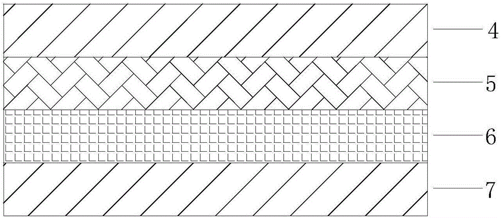
[0032] refer to figure 2 , the diaphragm of a kind of sounding device that the present invention provides, comprises first engineering plastics layer 4, adhesive film layer 5, elastomer layer 6, second engineering plastics layer 7 successively; Said first engineering plastics layer 4, adhesive film The layer 5, the elastomer layer 6, and the second engineering plastic layer 7 are bonded together through a composite process.

[0033] Same as Embodiment 1, in this embodiment, the first engineering plastic layer 4 and the second engineering plastic layer 7 can use materials well known to those skilled in the art, such as polyether ether ketone, polyarylate, Polyetherimide, polyimide, polyphenylene sulfide, polyethylene naphthalate, polyethylene terephthalate, etc. For those skilled in the art, the materials of the first engineering plastic layer 4 and the second engineering plastic layer 7 can be the same or different, and those skilled in the art can choose according to actual...

Embodiment 3

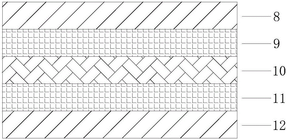
[0038] refer to image 3 , the vibrating membrane of a sounding device provided by the present invention sequentially includes a first engineering plastic layer 8, a first adhesive film layer 9, a second engineering plastic layer 10, a second adhesive film layer 11, and a third engineering plastic layer 12; The first engineering plastic layer 8 , the first adhesive film layer 9 , the second engineering plastic layer 10 , the second adhesive film layer 11 and the third engineering plastic layer 12 are bonded together through a composite process.

[0039] Same as Embodiment 1, in this embodiment, the first engineering plastic layer 8, the second engineering plastic layer 10, and the third engineering plastic layer 12 can adopt materials well known to those skilled in the art, such as polyether Ether ketone, polyarylate, polyetherimide, polyimide, polyphenylene sulfide, polyethylene naphthalate, polyethylene terephthalate, etc. For those skilled in the art, the materials of the ...


PUM


Abstract

The invention relates to a vibration diaphragm of a sound production device. The vibration diaphragm comprises a first engineering plastic layer, a second engineering plastic layer and a glue diaphragm layer located between the first engineering plastic layer and the second engineering plastic layer. The glue diaphragm layer is formed by coating and solidifying high-temperature-resistance glue. The elasticity modulus change value of the glue diaphragm layer from room temperature to 150 DEG C is smaller than 10%. The first engineering plastic layer, the glue diaphragm layer and the first engineering plastic layer are attached together through a compound technology. According to the vibration diaphragm, the high-temperature-resistance glue is coated and solidified to be diaphragm, and attached together with the first engineering plastic layer and the second engineering plastic layer in the mode of the glue diaphragm through the compound technology. Due to the fact that the glue diaphragm layer is good in high temperature resistance, the product can still have the good acoustic properties under high temperature, such as resonant frequency at normal temperature, low distortion, good tone quality and the like.

Description

technical field [0001] The present invention relates to a diaphragm, and more particularly, the present invention relates to a composite diaphragm used in a sound generating device. Background technique [0002] With the improvement of the quality of life, consumers have higher and higher requirements for sound quality, which requires higher and higher performance requirements for the speaker diaphragm in the audio system. Traditional loudspeaker diaphragms are mostly composite diaphragms. However, some limitations of the process structure of these composite diaphragms make the sound quality of the speakers unsatisfactory. [0003] Traditional composite diaphragms usually use adhesive films to achieve the bonding between multi-layer films. The structural characteristics of acrylic adhesive films determine that the speaker diaphragms that use them will inevitably have the following two defects: first , poor heat resistance. With the continuous introduction and application o...

Claims


Application Information

Patent Timeline
Patent Type & Authority Applications(China)
IPC IPC(8): H04R7/10
CPCH04R7/10H04R2207/021
Inventor 闫付臻刘成林吴增勋
Owner GOERTEK INC
Learn More