Press quenching machining tool with detection and circular ring part limiting devices

A molded quenching and limit device technology, which is applied in the direction of quenching device, heat treatment equipment, furnace, etc., can solve the problems of excessive variation of grinding wheel feed rate, uneven grinding amount, damage to workpiece equipment, etc., to improve processing efficiency and Pass rate, convenient operation and control, and high degree of automation

Active Publication Date: 2016-08-24
NINGXIA MACHINERY RES INST
View PDF10 Cites 5 Cited by
  • Summary
  • Abstract
  • Description
  • Claims
  • Application Information

AI Technical Summary

Problems solved by technology

[0004] At present, all railway bearing molding quenching presses used online in China are mainly to control the deformation of the raceway of the jacket workpiece during the quenching process. The tooth mouth refers to the thinner ring part at both ends of the railway bearing jacket, and the deformation of the tooth mouth has never been uniform. A reasonable mechanism is used for effective control. During the quenching process, the workpiece starts to shrink and hold the mold tightly after rapid cooling. Because the thickness of the tooth mouth is thinner, it first shrinks in place, and the workpiece raceway and the middle part are thicker and unsealed, and will continue to shrink inward. During the contraction process of this part, it will cause different degrees of external expansion and deformation of the mouth mouth, resulting in uncontrollable deformation of the mouth mouth
[0005] Since the traditional processing procedure after quenching, that is, the grinding process is a separate process for the raceway and the tooth gap, it can make up for the shortcomings caused by the large deformation of the tooth gap, but due to the need for two clamping and processing, the processing efficiency is low
With the popularization of intelligent manufacturing and the improvement of automation in enterprises, various railway bearing manufacturers use intelligent grinding machines for one-time grinding of the raceway and the tooth gap for the jacket workpiece. If the deformation of the tooth gap is too large and the concentricity with the raceway If the height cannot be matched, it will bring a very big problem to the one-time grinding process, and the following problems will occur: 1. The grinding of the teeth or the raceway is not in place; 2. Due to the large deformation of the teeth, the grinding wheel enters the grinding process Excessive changes in the amount of knife will quickly reduce or damage the service life of the grinding wheel; 3. The grinding amount is uneven and the scrap rate increases, which seriously affects the production efficiency and economic benefits of the enterprise, and there are certain safety hazards
[0006] And in the actual use of the railway bearing molding quenching press, sometimes the jacket workpiece cannot be removed from the mold after quenching, that is, the workpiece and the mold are not completely separated.
According to the analysis of the mold structure of the equipment, there are three situations in which the mold cannot be removed: one is that the workpiece and the upper and lower molds are not separated, and the rise of the main oil cylinder is blocked at this time. Issue a displacement delay alarm; the second is the adhesion between the workpiece and the lower mold. In this case, the feeding and discharging manipulator will issue a grasping delay alarm when discharging, that is, if the manipulator does not rise after 3-5 seconds, it means that the workpiece and the lower mold The mold is not disengaged; the third is the adhesion between the workpiece and the upper mold. There is no preventive means and alarm function for this situation. Since the entire quenching process is carried out in a closed environment, this phenomenon is not easy to be discovered by the operator. If The workpiece adheres to the upper mold without being found. When the next cycle of red-hot workpiece is in place, the moving beam will still automatically lower, causing serious damage to the workpiece and even the equipment, directly affecting the production efficiency and economic benefits of the enterprise.

Method used


Image

  • Press quenching machining tool with detection and circular ring part limiting devices
  • Press quenching machining tool with detection and circular ring part limiting devices
  • Press quenching machining tool with detection and circular ring part limiting devices

Examples


Embodiment Construction

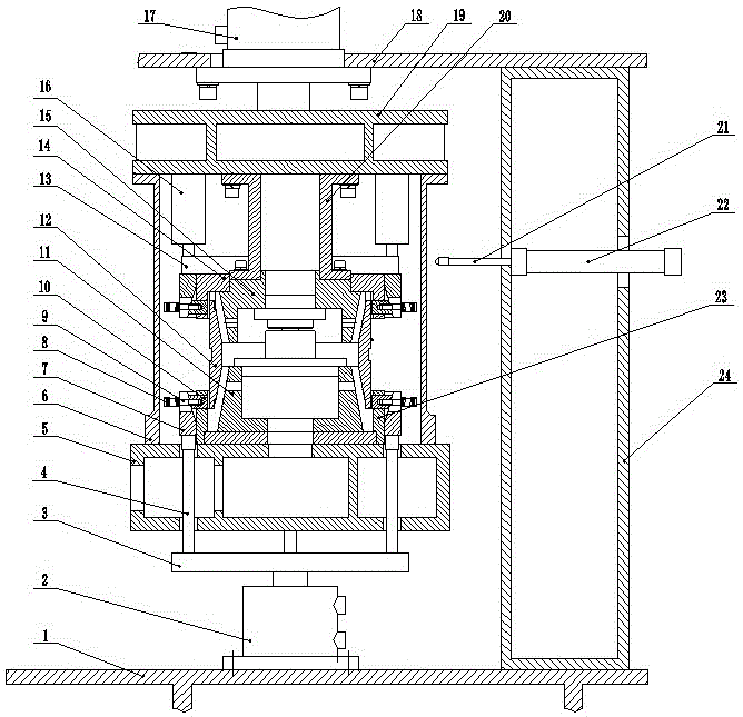
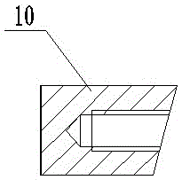
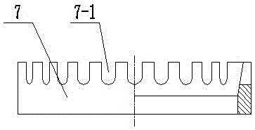
[0029] exist figure 1 , 2 , 3, 4, 5, 6, 1-main base, 2-lower mold cylinder, 3-lower pressure ring, 4-connecting rod, 5-worktable, 6-quenching oil cover, 7-annular inner cone Body, 7-1-"U-shaped groove", 8-spring, 9-screw, 10-limiting block, 11-lower mold, 12-workpiece, 13-upper pressure ring, 14-upper limit block guide seat, 15 - Upper mold, 16 - Upper mold oil cylinder, 17 - Main oil cylinder, 18 - Upper beam, 19 - Moving beam, 20 - Upper mold seat, 21 - Probing head, 22 - Cylinder for detection, 23 - Guide seat of lower limit block , 23-1-limiting block guide hole, 24-column.

[0030] like figure 1 As shown, the lower mold cylinder 2 is installed on the main base 1, the lower end of the disc-shaped lower pressure ring 3 is connected with the piston rod in the lower mold cylinder, and the upper plane of the lower pressure ring is fixedly equipped with a connecting rod 4, which passes through the The workbench 5 is connected to the lower end surface of the ring-shaped inne...


PUM


Abstract

The invention relates to a quenching device and in particular relates to a press quenching machining tool with detection and circular ring part limiting devices. The machining tool comprises a main machine base, a workbench, an upright column, a lower die, a quenching oil shield and an upper die, wherein the lower die is installed on the workbench; the quenching oil shield is installed on a moving cross beam; and the upper die is installed in the quenching oil shield. The machining tool is characterized in that annular inner cones and limiting block guide bases are arranged in the positions of workpiece circular ring parts of the upper and lower dies; limiting blocks are installed in the limiting block guide bases; an air cylinder, a workpiece detection head and a position detection switch are installed on the upright column; the air cylinder is used for detection; and the detection switch is connected with an electrical control part of the press quenching machining tool. The device can achieve the effects of effectively controlling deformation of workpiece circular ring parts and roller paths in the quenching process, effectively reducing the phenomenon of severe damages, caused because the workpieces and the upper die are not separated, of workpieces and even equipment, effectively improving the coaxiality of the workpiece circular ring parts and roller paths, effectively reducing the grinding amount of later machining and increasing the machining efficiency and percent of pass of the products.

Description

Technical field [0001] The invention relates to a quenching device, in particular to a die-press quenching machine tool with a detection and tooth gap limiting device. Background technique [0002] For the sleeve parts that need quenching treatment in the mass processing process, quenching heat treatment is one of the key processes that determine product quality, performance and life. The quenching heat treatment process belongs to thermal processing, and there are many unpredictable factors, such as railway bearings In the manufacturing process of the inner and outer rings, qualified products processed before the process, in the quenching process, after high-temperature heating for a long time, and rapid cooling during quenching, changes in geometric size and shape will inevitably occur. When the deformation is too large , a large number of substandard products will be produced, and the rework rate and scrap rate are high. [0003] At present, for the heat treatment of lar...

Claims


Application Information

Patent Timeline
Patent Type & Authority Applications(China)
IPC IPC(8): C21D1/673C21D9/40C21D11/00
CPCC21D1/673C21D9/0062C21D9/40C21D11/00
Inventor 王国升许军晓李翔
Owner NINGXIA MACHINERY RES INST
Why Eureka
Try Eureka