Design and calculation method for inner conductor of quasi-microstrip ferrite circulator

A design calculation and ferrite technology, which is applied to waveguide devices, electrical components, circuits, etc., and can solve the problems of difficult design and debugging, complex structure of ferrite circulators, and poor temperature performance.

Active Publication Date: 2016-08-24
MIANYANG NAITE ELECTRONICS IND
View PDF5 Cites 1 Cited by
  • Summary
  • Abstract
  • Description
  • Claims
  • Application Information

AI Technical Summary

Problems solved by technology

However, due to their inherent characteristics, they have their own shortcomings in terms of comprehensive performance. For example, ferrite circulators designed according to distributed parameters are bulky; ferrite circulators designed according to lumped parameters have complex structures and large insertion loss. , poor temperature performance; while the microstrip conductor of the microstrip ferrite circulator is directly vapor-deposited on the ferrite surface by photolithography and vacuum coating, and the production process involves ferrite grinding, polishing, photolithography, Vacuum coating and other complicated processes, and difficult to design and debug, poor performance stability and solder resistance of input and output ports
What is even more regrettable is that for a long time, among the above-mentioned various design techniques, pure theory and conceptual design methods are mostly used, lacking complete design procedures, clear calculation methods and accurate calculation results, so that often in the trial production of new products With a lot of blindness, time-consuming and expensive

Method used


Image

  • Design and calculation method for inner conductor of quasi-microstrip ferrite circulator
  • Design and calculation method for inner conductor of quasi-microstrip ferrite circulator
  • Design and calculation method for inner conductor of quasi-microstrip ferrite circulator

Examples


Embodiment Construction

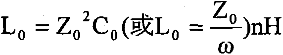
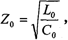
[0007] 1. Parallel inductance L composed of triangular inner conductors 0 and capacitance C 0 Calculation of : In the ideal case of ignoring the electromagnetic loss, L 0 C 0 When a parallel circuit resonates, it is a low impedance circuit, and its characteristic impedance value According to the document "Jiang Renpei, Xu Jidong "Thin Type Strip Line Circulator with internal matching LC-networks" 10th international Conference on microwave Ferrites PP344-348september 1990", the impedance value is between 10 and 20 ohms. When angular frequency ω = 1 L 0 C 0 , get:

[0008] C 0 = 1 ω Z 0 ...


PUM


Abstract

The invention relates to a design and calculation method for an inner conductor of a quasi-microstrip ferrite circulator. The design and calculation method for the inner conductor of the quasi-microstrip ferrite circulator belongs to the technical field of communication electronic component and assembly design. According to the invention, a thin copper strip is utilized to replace a microstrip conductor evaporated at the surface of a ferrite so as to form a quasi-microstrip inner conductor. A triangular part of the inner conductor forms a shunt inductor L0 and a capacitor C0, three leading-out ports are mutually of 120-degree rotational symmetry, each narrow-band line forms an inductor LP, and each broad-band line forms a capacitor CP. The upper surface and the lower surface of the inner conductor are closely contacted with an upper aluminum cavity and a lower aluminum cavity respectively through the ferrite, and the upper aluminum cavity and the lower aluminum cavity are connected by four screws so as to form a shunt metal-ferrite-metal interlayer capacitor. The design and calculation method solves a key technological problem that the shunt inductor L0, the capacitor C0, the inductors LP and the capacitors CP are difficult to be accurately calculated by mathematics for a long time; and a formula for calculating the diameter D of the area of the capacitors (C0+3CP) formed by the inner conductor, the area AP of the capacitor CP formed by the broad-band line and the length lP of the inductor LP formed by the narrow-band line is derived. A calculation result relatively conforms to the reality, the blindness in new product trial-manufacture is reduced, and the method has a push and promotion effect for industrial technology development.

Description

(1) Technical field [0001] The invention belongs to the technical field of communication electronic components and component design. (2) Background technology [0002] According to microwave engineering principles and ferrite physics, gyromagnetic ferrite is a ferrimagnetic material with both gyromagnetism and dielectric properties. 0 The tensor magnetic permeability generated under the joint action of the radio frequency signal is the theoretical basis for the work of the ferrite circulator. The ferrite circulator has three ports. Due to the existence of tensor magnetic permeability, the ferrite circulator has non-reciprocity. If the signal is transmitted from port 1→2→3, then from port 3→2→ 1 becomes the isolation direction; using this characteristic, the ferrite circulator can be used as a duplexer in the communication system to realize the automatic conversion of the transmitted signal and the received signal. If one port (such as port 3) of the ferrite circulator is c...

Claims


Application Information

Patent Timeline
Patent Type & Authority Applications(China)
IPC IPC(8): H01P1/387
Inventor 全胜其他发明人请求不公开姓名
Owner MIANYANG NAITE ELECTRONICS IND
Why Eureka
Try Eureka