Implantable medical equipment charging system based on wireless energy transmission technology
A wireless energy transmission, implantable medical technology, applied in the direction of collectors, electric vehicles, electrical components, etc., can solve the problems of not meeting people's needs, the transmission distance can only reach the millimeter level, etc., to reduce pain and medical costs. , high safety, easy to use effect
- Summary
- Abstract
- Description
- Claims
- Application Information
AI Technical Summary
Problems solved by technology
Method used
Image
Examples
Embodiment 1
[0029] Embodiment 1 General framework of the present invention
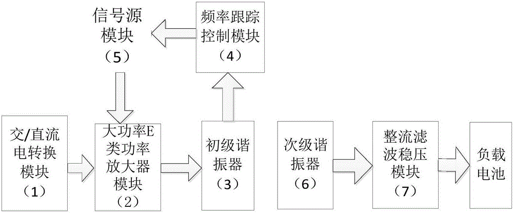
[0030] refer to figure 1 , the structure of the implantable medical device charging system based on the magnetic coupling resonant wireless energy transmission technology of the present invention includes an AC / DC conversion module 1, a high-power Class E amplifier module 2, a primary resonator 3, and a frequency tracking control module 4 , a signal source module 5, a secondary resonator 6 and a rectifying, filtering and stabilizing module 7. Among them, the AC / DC conversion module is responsible for converting the 220V AC we use daily into the low-voltage DC used by the system to provide power for the system. This module has a 18V-36V voltage output terminal, a +5V voltage output terminal and a -5V voltage output terminal. Voltage output terminal; the high-power Class E amplifier module is responsible for converting the DC power of module 1 into high-frequency AC power and sending it to the primary resonator; t...
Embodiment 2
[0031] Embodiment 2 AC / DC conversion module 1 of the present invention
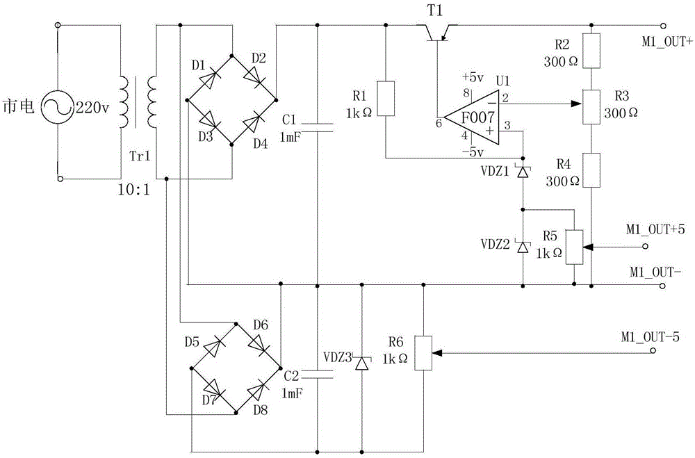
[0032] refer to figure 2 , the structure of the AC / DC conversion module 1 is as follows: the input terminal of the transformer Tr1 is connected to 220V mains, and an output terminal of the transformer Tr1 is connected to the cathode of the diode D1, the anode of the diode D2, the cathode of the diode D5, and the anode of the diode D6. The anodes are connected together, and the other output terminal is connected with the cathode of diode D3, the anode of diode D4, the cathode of diode D7, the anode of diode D8, the anode of diode D1, the anode of diode D3, the cathode of diode D6 and the diode D8 The cathodes of the diodes are connected together as the output cathode of the AC / DC conversion module 1, denoted as port M1_OUT-, the cathodes of the diode D2, the cathode of the diode D4, one end of the capacitor C1, one end of the resistor R1, and the collector of the transistor T1 are connected to Together, ...
Embodiment 3
[0033] Embodiment 3 High-power class E power amplifier module 2 of the present invention
[0034] refer to Figure 5 , the structure of the high-power class E amplifier module 2 is: one end of the capacitor C3 is connected to one end of the inductor L1 and used as the positive pole of the input terminal of the high-power class E amplifier module 2, which is denoted as port M2_IN+, and the other end of the inductor L1 is connected to the inductor One end of L2, one end of capacitor C4, and the drain of MOS transistor Q1 are connected, the other end of capacitor C4 is connected to one end of capacitor C5, the source of MOS transistor Q1, and the drain of MOS transistor Q2, and the other end of inductor L2 is connected to the capacitor One end of C6 is connected, the other end of capacitor C6 is connected to one end of capacitor C7, the other end of capacitor C7 is connected to one end of capacitor C8, and is used as the positive output terminal of the high-power class E amplifie...
PUM
 Abstract
Description
Claims
Application Information
 - R&D
- Intellectual Property
- Life Sciences
- Materials
- Tech Scout
- Unparalleled Data Quality
- Higher Quality Content
- 60% Fewer Hallucinations
Browse by: Latest US Patents, China's latest patents, Technical Efficacy Thesaurus, Application Domain, Technology Topic, Popular Technical Reports.
© 2025 PatSnap. All rights reserved.Legal|Privacy policy|Modern Slavery Act Transparency Statement|Sitemap|About US| Contact US: help@patsnap.com


