Double-side polishing device and method capable of controlling rigidity of polishing pad through cluster dynamic magnetic field

A dynamic magnetic field and double-sided polishing technology, which is applied in the direction of grinding drive devices, surface polishing machine tools, grinding/polishing equipment, etc., can solve the problems of inconsistent relative speed and uneven processing of workpieces, and achieve good consistency and low cost. The effect of low cost and high processing efficiency

Active Publication Date: 2016-08-31
GUANGDONG UNIV OF TECH
View PDF6 Cites 14 Cited by
  • Summary
  • Abstract
  • Description
  • Claims
  • Application Information

AI Technical Summary

Problems solved by technology

[0004] The embodiment of the present invention provides a double-sided polishing device and method for controlling the rigidity of the polishing pad by a cluster dynamic magnetic field. By adjusting the rigidity of the flexible polishing pad, the whole process from rough polishing to fine polishing on both sides of the workpiece can be realized, and at the same time, the different workpieces in the traditional processing process can be solved. The relative speed between the position and the polishing pad is not consistent, resulting in uneven processing of the workpiece

Method used


Image

  • Double-side polishing device and method capable of controlling rigidity of polishing pad through cluster dynamic magnetic field
  • Double-side polishing device and method capable of controlling rigidity of polishing pad through cluster dynamic magnetic field
  • Double-side polishing device and method capable of controlling rigidity of polishing pad through cluster dynamic magnetic field

Examples


Embodiment 1

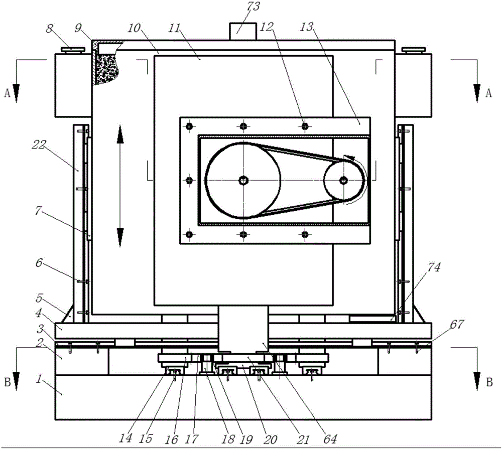
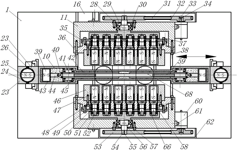
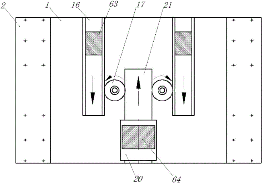
[0046] Such as figure 1 with figure 2 As shown, a double-sided polishing device for controlling the stiffness of a polishing pad by a cluster dynamic magnetic field is characterized in that it includes a variable stiffness cluster magnetron polishing pad generating mechanism, a workpiece fast clamping mechanism and a workpiece motion drive mechanism, and the variable stiffness cluster magnetron The polishing pad generating mechanism includes base (1), screw two (12), linear guide rail (14), screw three (15), precision single-sided rack (16), gear (17), gear shaft (18), deep Groove bearing (19), precision double-sided rack (21), connecting plate one (63), connecting plate two (64), grooved end cover (9), housing (11), screw four (28), main shaft Eccentric distance (29), rolling bearing (30), V-shaped belt (31), small pulley (32), motor shaft (33), small flat key (34), bearing cover plate (35), bearing seat plate (36) , screw five (37), screw six (38), magnet mount (46), cyli...

Embodiment 2

[0056] Using the polishing method of the double-sided polishing device using the cluster dynamic magnetic field to control the stiffness of the polishing pad, the steps of performing double-sided polishing pads on a square TFT-LCD glass substrate with a size of 100mm×100mm are as follows:

[0057] 1) According to the size and material properties of the TFT-LCD glass substrate, design a double-sided polishing device that matches the workpiece size with a cluster dynamic magnetic field to control the stiffness of the polishing pad. Magnet (47) is installed in the double-sided polishing device of cluster dynamic magnetic field control polishing pad rigidity, and rotating rotary handle (8) makes the magnetic pole direction of bar-shaped permanent magnet (25) and square magnet (39) vertical, prepares and workpiece shape and Circular cage with suitable thickness;

[0058] 2) According to the shape of the TFT-LCD glass substrate, use acid and alkali corrosion-resistant plastics to ma...

Embodiment 3

[0068] The difference between this embodiment and Embodiment 2 is that this embodiment is to perform double-sided polishing on a single crystal silicon substrate with a diameter of 100mm, and the polishing method of the double-sided polishing device for controlling the stiffness of the polishing pad by a cluster dynamic magnetic field of the present invention includes the following step:

[0069] 1) According to the size and material properties of the single crystal silicon substrate, design a double-sided polishing device that matches the size of the workpiece with a cluster dynamic magnetic field to control the stiffness of the polishing pad. Magnet (47) is installed in the double-sided polishing device of cluster dynamic magnetic field control polishing pad rigidity, and rotating rotary handle (8) makes the magnetic pole direction of bar-shaped permanent magnet (25) and square magnet (39) vertical, prepares and workpiece shape and Circular cage with suitable thickness;

[...


PUM

PropertyMeasurementUnit
magnetic flux densityaaaaaaaaaa

Abstract

The embodiment of the invention discloses a double-side polishing device and method capable of controlling the rigidity of a polishing pad through a cluster dynamic magnetic field. The whole process from rough polishing to fine polishing of both sides of a workpiece is achieved by adjusting the rigidity of the flexible polishing pad, and the problem that in the traditional machining process, machining of the workpiece is nonuniform due to the fact that the relative speed between different positions of the workpiece and the polishing pad is inconsistent is solved. The double-side polishing device capable of controlling the rigidity of the polishing pad through the cluster dynamic magnetic field comprises a variable-rigidity cluster magnetic-control polishing pad generating mechanism, a workpiece fast clamping mechanism and a workpiece movement driving mechanism, wherein the variable-rigidity cluster magnetic-control polishing pad generating mechanism comprises a first magnetic field generating block and a second magnetic field generating block which are arranged symmetrically; the first magnetic field generating block and the second magnetic field generating block each comprise a shell, a deflection spindle, an eccentric camshaft, a magnetic mounting seat, permanent magnets and a motor; the workpiece fast clamping mechanism comprises a working slot, a clamping plate, a connecting rod, a hinge plate, a fixed hinge, a square magnet, an electrical soft iron block, annular cast iron and a strip-shaped permanent magnet; and the workpiece movement driving mechanism comprises a supporting block, a crossbeam, a horizontal linear motor, a vertical beam and a vertical linear motor.

Description

technical field [0001] The invention relates to a double-sided polishing device and method for controlling the rigidity of a polishing pad by a cluster dynamic magnetic field, which is particularly suitable for flattening processing of optoelectronic / microelectronic semiconductor substrates and optical elements, and belongs to the technical field of ultra-precision processing. Background technique [0002] Microelectronics and optoelectronics manufacturing represented by integrated circuit (IC) and optoelectronic device manufacturing is the core of the electronic information industry, and it is also the most competitive and fastest-growing industry in the world today. Single crystal silicon (Si), single crystal germanium (Ge), gallium arsenide (GaAs), single crystal silicon carbide (SiC) and sapphire (Al 2 o 3 ), etc., as substrate materials for integrated power electronic devices and optoelectronic devices, require ultra-flat, ultra-smooth (roughness Ra below 0.3nm), defec...

Claims


Application Information

Patent Timeline
Patent Type & Authority Applications(China)
IPC IPC(8): B24B31/10B24B7/17B24B27/00B24B41/02B24B47/04B24B47/16B24B41/06C09K3/14
CPCB24B7/17B24B27/0076B24B31/102B24B41/02B24B41/06B24B47/04B24B47/16C09K3/1409C09K3/1454
Inventor 潘继生阎秋生李卫华
Owner GUANGDONG UNIV OF TECH
Why Eureka
Try Eureka