
Composite energy storage power supply and method for realizing stabilization of DC bus voltage through composite energy storage power supply

A DC bus voltage, DC bus technology, applied in battery circuit devices, current collectors, electric vehicles, etc., can solve the problem of inconvenient realization of super capacitor and battery energy management, inconvenient management of super capacitor and battery energy, and disadvantageous DC bus. Voltage stability and other issues, to achieve the effect of extending life, high power density, and improving performance

Active Publication Date: 2016-08-31
CHINA NORTH VEHICLE RES INST
View PDF3 Cites 9 Cited by
  • Summary
  • Abstract
  • Description
  • Claims
  • Application Information

AI Technical Summary

Problems solved by technology

[0003] Generally speaking, the supercapacitor cannot be directly connected in parallel with the battery, because the voltage characteristics of the two are very different, it is difficult to match, and it will cause inconvenience to the energy management of the supercapacitor and the battery.
The parallel connection between supercapacitor and battery generally needs to be connected to DC / DC. There are two connection methods. One is to connect DC / DC before the supercapacitor and then connect it in parallel with the battery. The impact of discharge; one form is to connect the DC / DC in front of the battery, and then connect to the super capacitor, but this may cause large fluctuations in the DC bus voltage; these two structures are not conducive to controlling the stability of the DC bus voltage, and cannot be conveniently Enabling Energy Management for Supercapacitors and Batteries

Method used


Image

  • Composite energy storage power supply and method for realizing stabilization of DC bus voltage through composite energy storage power supply
  • Composite energy storage power supply and method for realizing stabilization of DC bus voltage through composite energy storage power supply
  • Composite energy storage power supply and method for realizing stabilization of DC bus voltage through composite energy storage power supply

Examples


Embodiment Construction

[0033] In order to make the purpose, content, and advantages of the present invention clearer, the specific implementation manners of the present invention will be further described in detail below in conjunction with the accompanying drawings and embodiments.

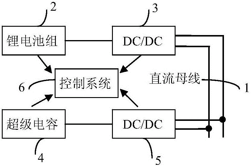
[0034] Such as figure 1 As shown, the present invention provides a composite energy storage power supply, including a DC bus 1, a lithium battery pack 2, a supercapacitor 4, a first bidirectional DC / DC 3, a second bidirectional DC / DC 5 and a control system 6;

[0035] The lithium battery pack 2 is connected to the DC bus 1 through the first bidirectional DC / DC 3, and the supercapacitor 4 is connected to the DC bus 1 through the second bidirectional DC / DC 5;

[0036] The lithium battery pack 2 and the supercapacitor 4 all have corresponding management systems, which are called battery management system and supercapacitor management system respectively. The battery management system is used to detect the voltage, current...


PUM


Abstract

The invention relates to a composite energy storage power supply and a method for realizing stabilization of DC bus voltage through the composite energy storage power supply, and belongs to the technical field of the energy storage power supply. A battery and a super-capacitor are connected with DC / DC, and then DC / DC is connected in parallel with the composite power supply structure so that isolation of voltage of the lithium ion battery, voltage of the super-capacitor and voltage of a DC bus can be realized, energy storage units are flexibly configured, energy management is convenient, impact of high current to the battery can be effectively avoided and the performance of the composite power supply can be enhanced. According to the voltage stabilization control method, the advantages of high power density and long cycle life of the super-capacitor can be effectively exerted, and the service life of a composite power supply energy storage system can be prolonged. Meanwhile, voltage of the DC bus can be effectively stabilized by the voltage stabilization control method.

Description

technical field [0001] The invention relates to the technical field of energy storage power supplies, in particular to a composite energy storage power supply and a method for stabilizing a DC bus voltage using the same. Background technique [0002] The current battery technology, especially lithium-ion battery technology, is developing rapidly. Lithium-ion batteries have been widely used in the field of energy storage. However, lithium batteries are difficult to meet the instantaneous high-power demand, and frequent high-current charging and discharging have greatly shortened the life of lithium batteries. Therefore, in In scenarios requiring high power, such as hybrid vehicles, electric vehicles, etc., a composite power supply mode is proposed. Composite power refers to the form of supercapacitors connected in parallel with batteries. Supercapacitors have a long cycle life and high power density, while batteries have high energy density. The combination of the two can e...

Claims


Application Information

Patent Timeline
Patent Type & Authority Applications(China)
IPC IPC(8): H02J7/34
CPCH02J7/345
Inventor 刘胜利张思宁李申戚于飞王美靖李艳明党寻诣
Owner CHINA NORTH VEHICLE RES INST
Learn More