Kitchen waste smashing, stirring and fermenting device

A technology for stirring fermentation and kitchen waste, which is applied in the fields of organic fertilizer, sustainable manufacturing/processing, climate change adaptation, etc. It can solve the problems of waste collection, transportation and treatment, blockage of oily sewage drainage pipes, and difficult treatment, and achieve crushing And good fermentation effect, simple structure, easy to use

Inactive Publication Date: 2016-09-21
姜红成 +1
View PDF9 Cites 4 Cited by
  • Summary
  • Abstract
  • Description
  • Claims
  • Application Information

AI Technical Summary

Problems solved by technology

However, due to its high oil, high salt, high water content, and perishable characteristics, it is difficult to handle, which brings troubles to garbage collection, transportation, and disposal.
At present, there are mainly the following methods to deal with kitchen waste: one is incineration, which will emit pollutants and greenhouse gases; the other is landfill, which requires a special landfill site and is easy to pollute the soil and water sources at the landfill; the other is One is to discharge directly into the sewer after crushing, which is convenient and simple to operate, but it is easy to generate sewage and odor, breed germs and mosquitoes, and cause the spread of diseases. burden; there is another way to use food waste after fermentation treatment, which is an effective way to treat kitchen waste in a harmless and resourceful manner
But nowadays, the garbage disposal department generally collects kitchen waste from residents’ homes for centralized fermentation treatment. The collection and transportation process is cumbersome, and when disposing of kitchen waste, it is generally not crushed in advance, resulting in uneven fermentation and low fermentation efficiency.

Method used


Image

  • Kitchen waste smashing, stirring and fermenting device
  • Kitchen waste smashing, stirring and fermenting device
  • Kitchen waste smashing, stirring and fermenting device

Examples


Embodiment 1

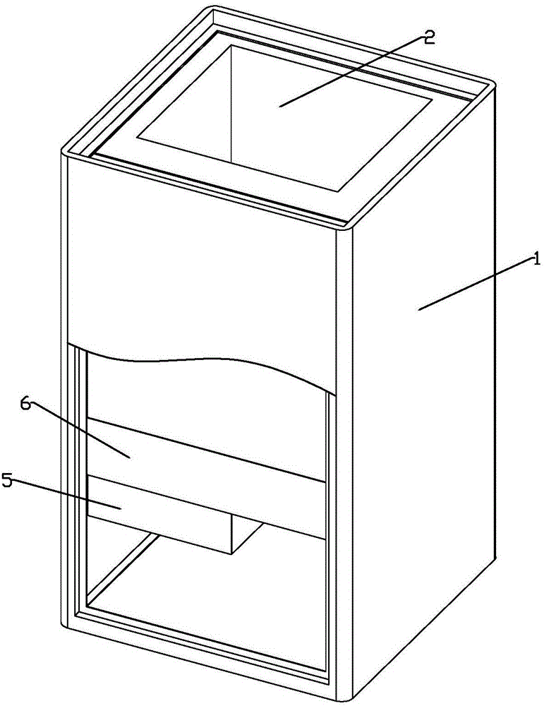
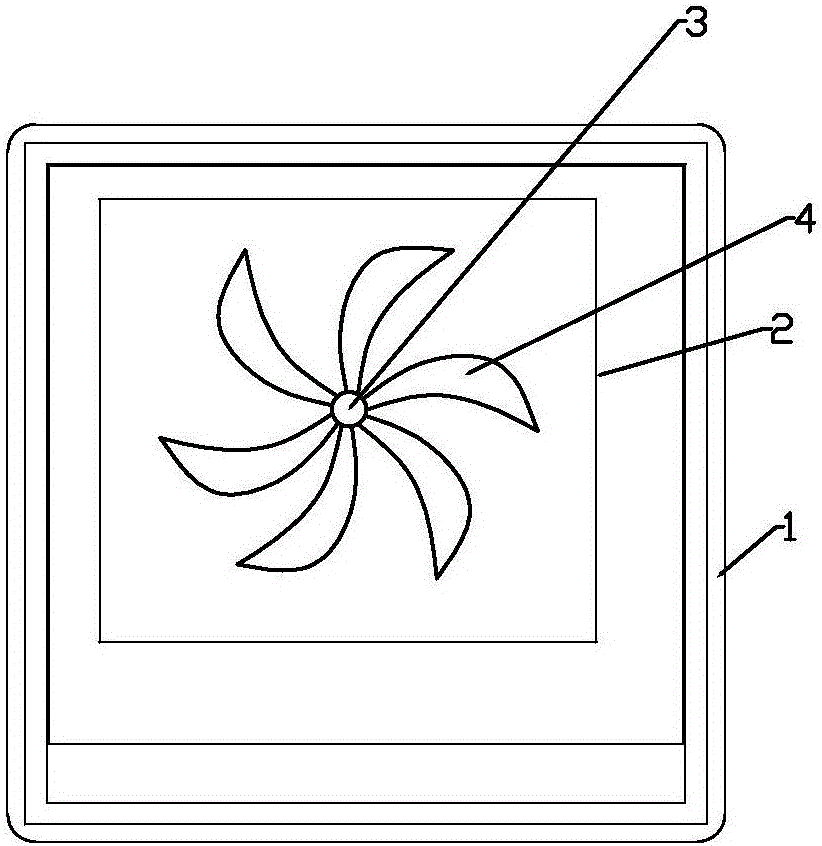
[0021] A kitchen waste crushing and stirring fermentation device, such as figure 1 and figure 2 As shown, it includes a shell 1 with one end closed and one end open, a stirring bin 2 located in the shell 1, a stirring linkage shaft 3, a crushing cutter 4 arranged on the stirring linkage shaft 3, a motor 5 and a heating device 6, the stirring linkage shaft At least one end of 3 is fixedly installed on the inner wall of the stirring bin 2, which is connected with the output shaft of the motor 5, the heating device 6 is arranged on the outer wall of the stirring bin 2, and the motor 5 is arranged on the outer wall of the stirring bin 2. Between the shell 1 and the mixing chamber 2.

[0022] Pour the kitchen waste into the mixing bin 2, start the food waste crushing and stirring fermentation device, the motor 5 drives the stirring linkage shaft 3, and the crushing knife 4 on the stirring linkage shaft 3 crushes the kitchen waste into fine particles, and at the same time puts in ...

Embodiment 2

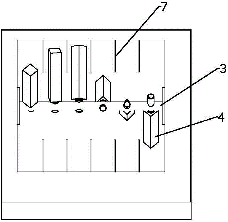
[0024] A kitchen waste crushing and stirring fermentation device, such as image 3 As shown, the difference from Example 1 is that: the two ends of the stirring linkage shaft 3 are respectively fixedly installed on the opposite inner walls of the stirring chamber 2, and the pulverizing cutters 4 are several pieces that are spirally installed on the stirring linkage shaft 3. A cuboid metal block with the same size and shape, the surface of the cuboid metal block is provided with several protrusions consistent with the axial direction of the stirring linkage shaft 3, which are fixed on the stirring linkage shaft 3 by screws, and the stirring linkage Auxiliary knives 7 are respectively installed on the inner walls of the mixing chamber 2 corresponding to both sides of the shaft 3. The auxiliary knives 7 are respectively composed of a number of metal plates with the same size and shape, which are arranged in parallel and evenly. The edges of the metal plates are serrated. The thic...

Embodiment 3

[0028] A kitchen waste crushing and stirring fermentation device, such as Figure 4 As shown, the difference from Example 2 is that an upper cover 8 is installed on the open end of the housing 1, the heating device 6 is a far-infrared heater, and the device also includes a deodorizing device 9, and the deodorizing device 9 9 Installed between the shell 1 and the mixing chamber 2, it is composed of a fan, an activated carbon filter layer, a honeycomb ceramic layer with a catalyst inside, an air inlet and an air outlet, and the air inlet is set on the inner wall of the mixing chamber 2 The air outlet is arranged on the outer wall of the housing 1 .

[0029] Installing the upper cover 8 at the top opening of the housing 1 is not only beneficial to the fermentation of the kitchen waste particles, but also prevents the indoor environment from being polluted by the kitchen waste and the gas generated by the fermentation of the kitchen waste. Harmful and odorous gases produced durin...


PUM

PropertyMeasurementUnit
thicknessaaaaaaaaaa
thicknessaaaaaaaaaa

Abstract

The invention provides a kitchen waste smashing, stirring and fermenting device which comprises a shell, a stirring bin, a stirring linkage shaft, a smashing cutter, a motor and a heating device. One end of the shell is closed, one end of the shell is open, the stirring bin is arranged in the shell, and the smashing cutter is disposed on the stirring linkage shaft. At least one end of the stirring linkage shaft is fixedly installed on the inner wall of the stirring bin and connected with an output shaft of the motor, the heating device is arranged on the outer wall of the stirring bin, and the motor is arranged between the shell and the stirring bin. The device integrates the smashing function, the stirring function and the fermenting function, is simple in structure, small in size, convenient to use, capable of being placed in a home to ferment kitchen waste and good in smashing and fermenting effect, fermentation broth can serve as fertilizer, and the environment-protecting and energy-saving functions are achieved.

Description

technical field [0001] The invention belongs to the technical field of garbage treatment, and in particular relates to a kitchen waste crushing, stirring and fermenting device. Background technique [0002] Kitchen waste is composed of starch, cellulose, protein, lipids and inorganic salts, etc. It contains a large amount of organic matter and rich in nitrogen, phosphorus, potassium, calcium and various trace elements, and has high utilization value. However, due to its high oil, high salt, high water content, and perishable characteristics, it is difficult to handle, which brings troubles to garbage collection, transportation, and disposal. At present, there are mainly the following methods to deal with kitchen waste: one is incineration, which will emit pollutants and greenhouse gases; the other is landfill, which requires a special landfill site and is easy to pollute the soil and water sources at the landfill; the other is One is to discharge directly into the sewer aft...

Claims


Application Information

Patent Timeline
Patent Type & Authority Applications(China)
IPC IPC(8): C05F9/02
CPCC05F9/02Y02P20/10Y02A40/20
Inventor 姜红成李超
Owner 姜红成
Why Eureka
Try Eureka