
Eureka
For R&D, Eureka makes reading and utilizing patents & technical documents easy.
Eureka AIR
Designed for self-driven R&D workflows. Generate viable solutions, solve complex R&D challenges, empower your innovation with AI.

Eureka Materials
Designed for material experts only. Revolutionize your material R&D, from search, analyze, to developing new materials.

TechResearch
Generate reliable direction feasibility study reports for your R&D in just a few steps.

TechSeek
Discover and master advanced knowledge NOW. Basics, ideas, possibilities, all at once.

TechMind
As an expert in R&D Theories, TechMind can generates customized viable solutions instantly.

TechRisk
Analyze your overall solution with one click, know your potential R&D risks in advance.

TechMonitor
Get weekly tech updates, stay abreast of the latest tech innovations and key insights.
Solid material energy comprehensive recovery system
A recovery system and solid material technology, which is applied in the field of solid material energy comprehensive recovery system, can solve the problems of large water resource consumption, inability to recycle heat energy, large floor space, etc., and achieve the effect of reducing downtime
- Summary
- Abstract
- Description
- Claims
- Application Information
AI Technical Summary
Problems solved by technology
Method used
Image

Examples
Embodiment 1
[0026] Such as figure 1 , 2 , 3, 4, 5, 6, and 7:
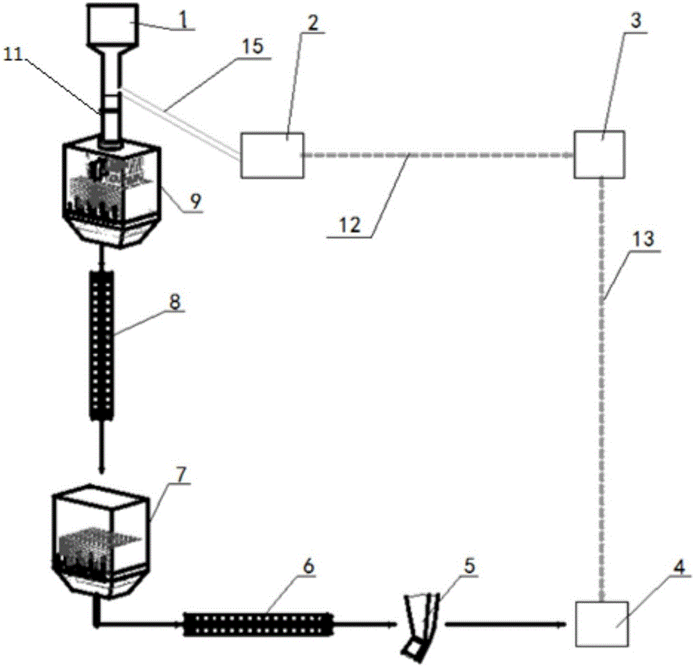
[0027] The present invention provides such figure 1 A solid material energy comprehensive recovery system shown includes a three-way slag discharge pipe 14, a high-temperature energy concentrator 9, a first scraper machine 8, a low-temperature energy collector 7, a second scraper machine 6, and end buffer feeding device 5;
[0028] The lower part of the three-way slag lowering pipe 14 is connected to the high temperature concentrator 9; the high temperature concentrator 9 is connected to the low temperature concentrator 7 through the first scraper machine 8; the low temperature concentrator 7 is connected to the low temperature concentrator 7 through the second scraper machine 6. Connect the end buffer feeding device 5.
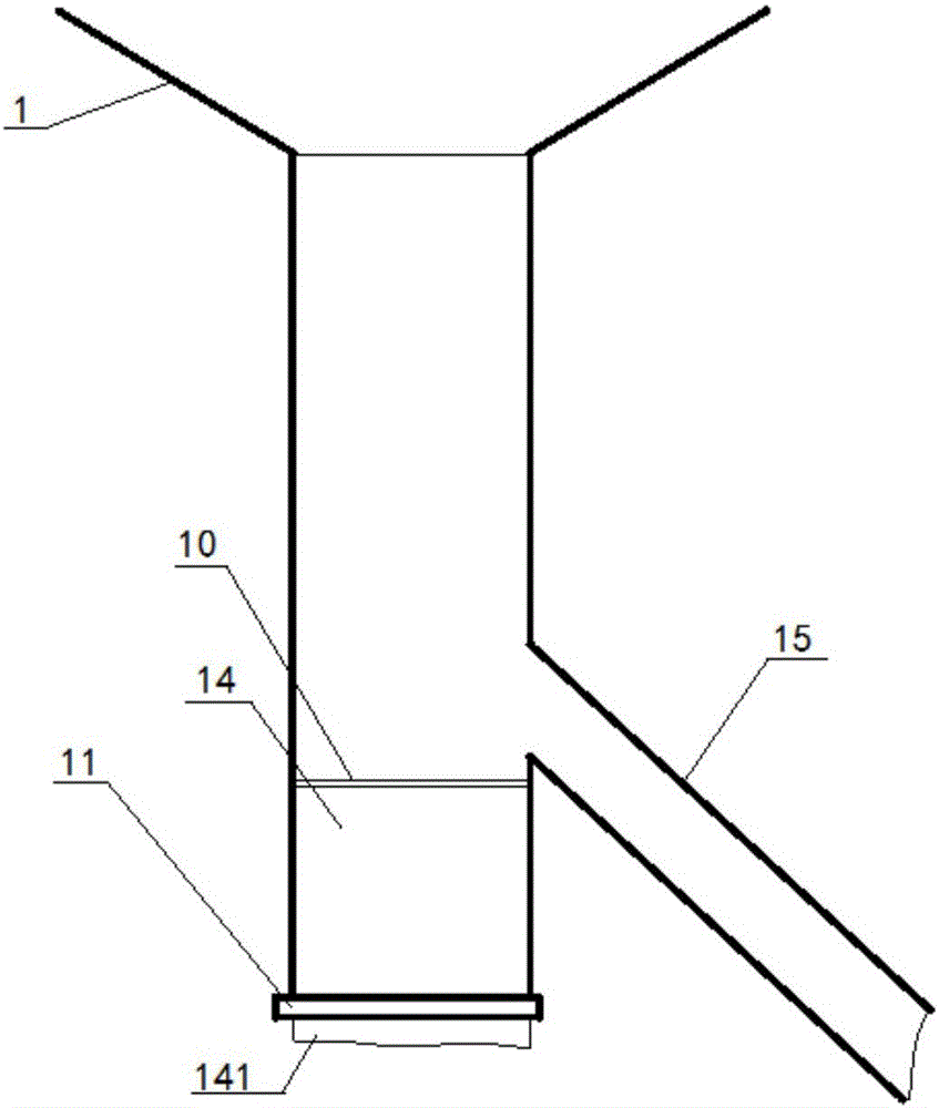
[0029] The upper part of the three-way slag lowering pipe 14 communicates with the fluidized fluidized furnace 1;
[0030] The side of the three-way slag lowering pipe communicates with the drum 2 throug...
Embodiment 2
[0035] Such as figure 1 , 2 , 3, 4, 5, 6, and 7:
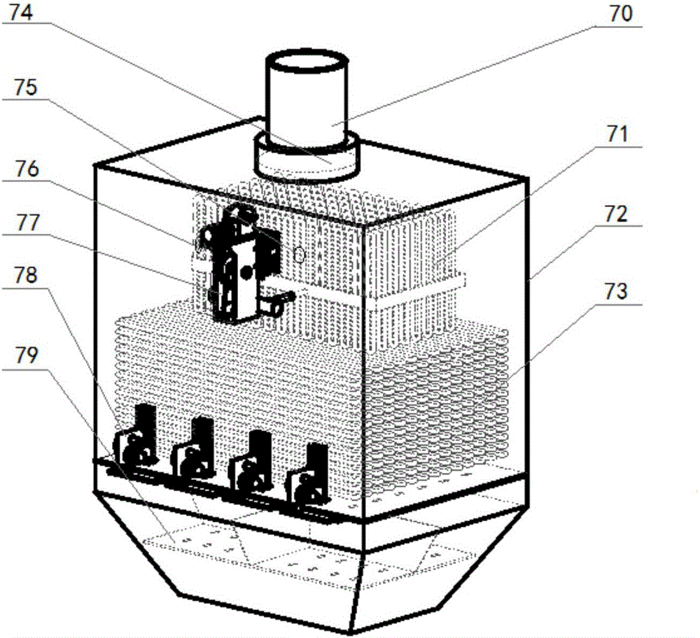
[0036] On the basis of Example 1, such as figure 2 , 7 As shown, the high-temperature energy concentrator 7 includes a box body 72 and a lower slag pipe 70 at the top of the box body 72, and a filter screen 74 is installed at the outlet of the lower slag pipe 70; There are upper pipes 71, lower pipes 73, and secondary lower hoppers 79; the outer wall of the box body 72 is provided with a discharge actuator 78 for controlling the action of the secondary lower hoppers;
[0037] A material level gauge 1 75 and a material level gauge 2 76 are arranged on the upper part of the box body 72 ; a vibrator 77 is installed on the outer wall of the box body 72 .
[0038] Such as figure 2 , 7 As shown, the high-temperature energy concentrator 7 is divided into upper and lower parts of the pipeline circulation and the box water wall circulation, and two incoming water (industrial water) are arranged inside; the upper half of the pip...
PUM
 Abstract
Description
Claims
Application Information
 - R&D Engineer
- R&D Manager
- IP Professional
- Industry Leading Data Capabilities
- Powerful AI technology
- Patent DNA Extraction
Browse by: Latest US Patents, China's latest patents, Technical Efficacy Thesaurus, Application Domain, Technology Topic, Popular Technical Reports.
© 2024 PatSnap. All rights reserved.Legal|Privacy policy|Modern Slavery Act Transparency Statement|Sitemap|About US| Contact US: help@patsnap.com