
A Simulation Test Method for Landslide Disaster in Soft Soil Layer

A technology for simulating experiments and disasters, applied in the field of geotechnical engineering, it can solve problems such as the inability to understand the law of influence, the complexity of the device structure, and the inability to analyze

Inactive Publication Date: 2018-07-06
西安心学交通地质工程有限公司
View PDF13 Cites 0 Cited by
  • Summary
  • Abstract
  • Description
  • Claims
  • Application Information

AI Technical Summary

Problems solved by technology

Existing observation methods for the expansion process of soil shear bands have problems such as complex device structure, high test cost, cumbersome test process, poor operability, and poor use effect to varying degrees. The most important thing is that they cannot be simple, fast and accurate. Analyzing the soil microstructure of the shear zone, it is impossible to understand the influence of the soil microstructure on the macroscopic performance of the soil shear zone, and it is impossible to establish the relationship between the soil microstructure characteristics of the soil shear zone and its macroscopic performance. contact
Correspondingly, it is impossible to realize the real simulation test of landslide disaster in soft soil layer

Method used


Image

  • A Simulation Test Method for Landslide Disaster in Soft Soil Layer
  • A Simulation Test Method for Landslide Disaster in Soft Soil Layer
  • A Simulation Test Method for Landslide Disaster in Soft Soil Layer

Examples


Embodiment 2

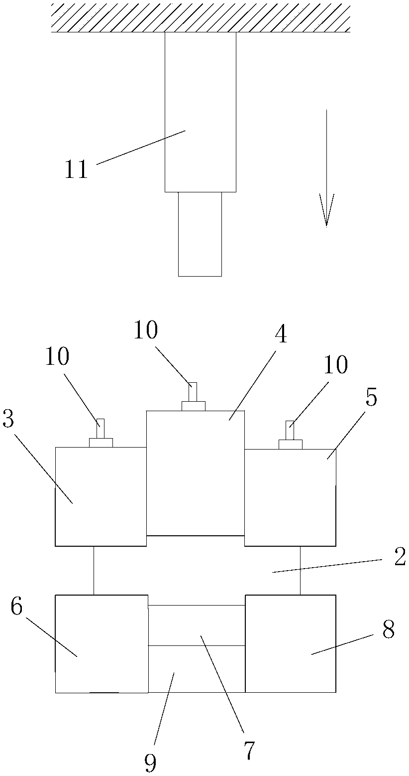
[0200] Such as Figure 5 As shown, in this embodiment, the difference from Embodiment 1 is that the shearing jig in step 201 further includes a limiting sleeve 12 fitted on the upper jig and outside the lower jig.

[0201] In this embodiment, the remaining method steps are the same as those in Embodiment 1.

Embodiment 3

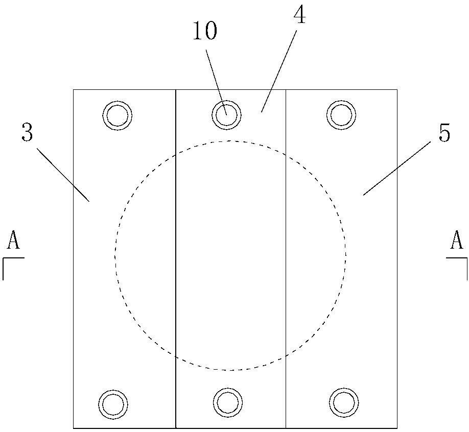
[0203] Such as Figure 6 , Figure 7 As shown, in this embodiment, the difference from Embodiment 1 is that the widths of the upper clamp and the lower clamp in step 201 are the same as the inner diameter of the earth taking ring cutter 2; the middle and lower clamping blocks only include Upper clamping block 7; the length, width and height of the upper left clamping block 3, the upper right clamping block 5, the lower left clamping block 6 and the lower right clamping block 8 are all the same, and the middle and upper clamping blocks 4 and The width and height of upper clamping block 7 are all identical with left upper clamping block 3, and the length of described middle upper clamping block 4 and upper clamping block 7 is identical and the length of both is greater than the length of left upper clamping block 3.

[0204] During actual processing, the lengths of the upper left clamping block 3, the upper right clamping block 5, the upper middle clamping block 4, the lower le...

Embodiment 4

[0212] In this example, the difference from Example 1 is that the curing solution described in step 203 is uniformly composed of epoxy resin, acetone, ethylenediamine and dibutyl phthalate in a volume ratio of 100:170:6:2.2 mixed.

[0213] In this embodiment, the remaining method steps are the same as those in Embodiment 1.


PUM

PropertyMeasurementUnit
heightaaaaaaaaaa

Abstract

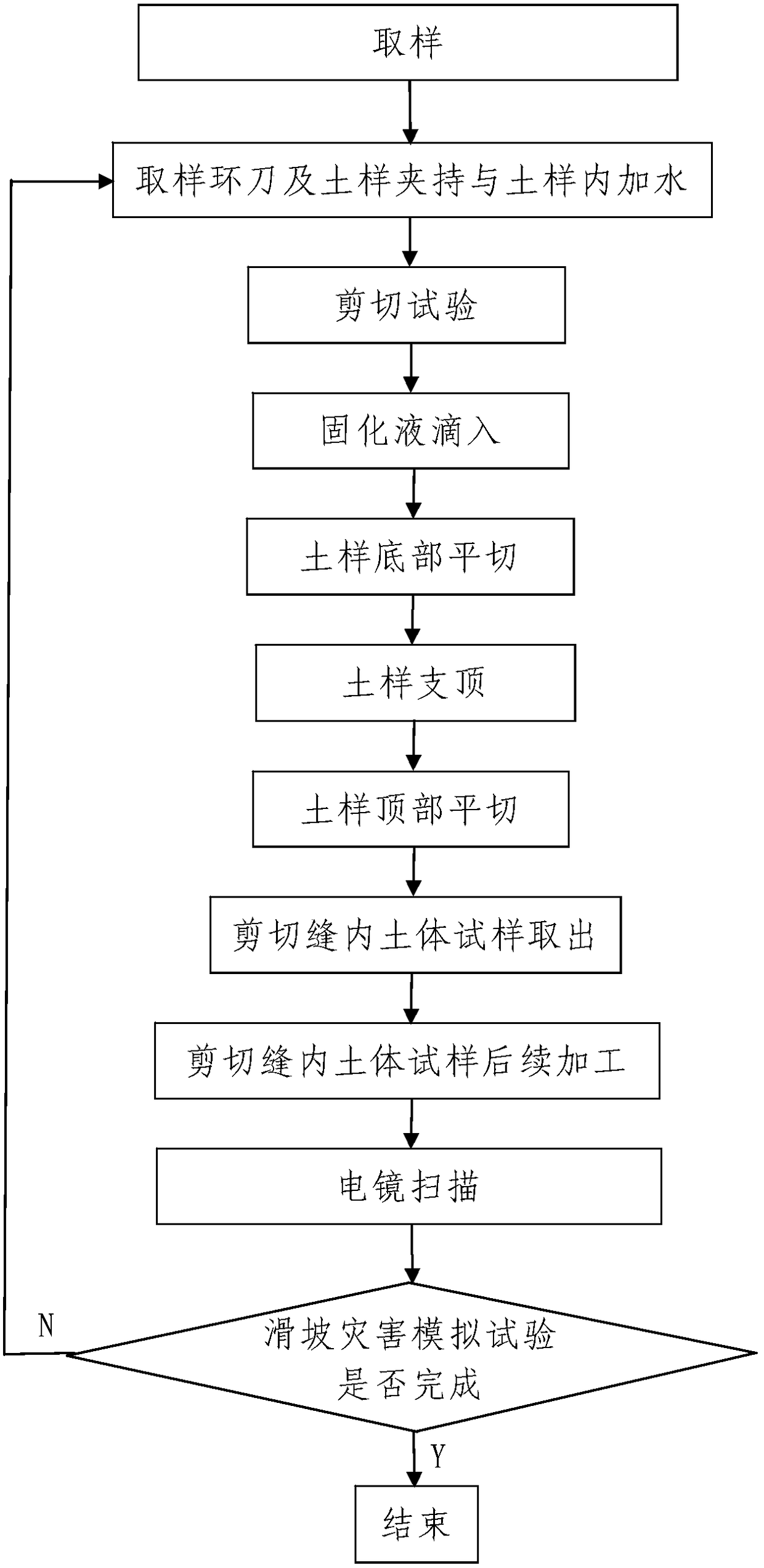
The invention discloses a simulation test method for the landslide hazard of a soft soil layer. The simulation test method comprises the following steps: (1) sampling; (2) landslide hazard simulation test: carrying out a simulation test on the landslide hazard of a to-be-tested sliding slope by virtue of N to-be-tested surfaces of a tested soil sample from top to bottom: (201) clamping a sampling ring knife and the soil sample, adding water into the soil sample; (202) carrying out a shear test; (203) dropping solidifying liquid; (204) transversely cutting the bottom of the soil sample; (205) supporting the soil sample; (206) transversely cutting the top of the soil sample; (207) taking out the soil sample in a shearing seam; (208) carrying out subsequent processing on the soil sample in the shearing seam; (209) carrying out electron microscope scanning; (210) carrying out the simulation test by virtue of the next to-be-tested surface; (211) repeatedly carrying out the step (210) for N-2 times, so as to finish the whole simulation test process; and (3) sorting shear simulation test results. The simulation test method is simple, the design is reasonable, the use effect is good, and the expansion process of a shear zone on the sliding slope can be effectively and truly simulated.

Description

technical field [0001] The invention belongs to the technical field of geotechnical engineering, and in particular relates to a simulation test method for landslide disasters in soft soil layers. Background technique [0002] In recent years, the transformation of the natural environment by human activities has become more and more intense. Human engineering activities have caused many geological disasters, which have caused great damage to people's lives and property. Among them, the slope instability induced by human activities is the most serious, and the focus of the study of slope instability is to study the deformation and expansion process of the soil shear zone. The shear zone refers to a strong deformation zone with shear strain developed in the lithosphere or soil mass, and the shear zone developed in the soil mass is a soil shear zone. This deformation zone can be a planar structure (fault) with strain discontinuity, or a ductile shear zone with continuous strai...

Claims


Application Information

Patent Timeline
Patent Type & Authority Patents(China)
IPC IPC(8): G01N33/24G01N1/04
CPCG01N1/04G01N33/24
Inventor 李晓军王晓华李昊李洁梁
Owner 西安心学交通地质工程有限公司
Learn More