CNC small modulus straight bevel gear planer

A technology of straight bevel gear and gear planer, which is applied in the direction of gear tooth manufacturing device, gear cutting machine, belt/chain/gear, etc., which can solve the problem of inability to use small modulus straight bevel gear planer and insufficient movement of the knife Agile, reliable, and unable to meet the knife height adjustment range, etc., to achieve the effect of small space occupation, compact structure layout, and large knife height adjustment range

Active Publication Date: 2018-03-20
通用技术集团天津第一机床有限公司
View PDF13 Cites 2 Cited by
  • Summary
  • Abstract
  • Description
  • Claims
  • Application Information

AI Technical Summary

Problems solved by technology

This structure has the following disadvantages: 1. The above-mentioned tool letting mechanism is installed between the tool holder base and the ram, and the structure is relatively complicated, so it cannot be applied to a compact small-module straight-tooth bevel gear planer; 2. The above-mentioned tool letting mechanism The knife letting and returning actions of the mechanism are clamped by the splint mechanism to let the knife pull rod swing the clamping plate, and the knife letting action is not agile and reliable; 3. The above knife letting mechanism cannot adjust the knife letting amount due to its structural limitations
During the use of the above structure, there will often be problems such as damage to the wedge surface due to insufficient wedge pin strength or self-locking due to insufficient wedge angle, resulting in failure of the knife height adjustment function; in addition, due to the limitation of the part size, there will be There is a problem that the tool height adjustment range cannot be met due to the short wedge surface

Method used


Image

  • CNC small modulus straight bevel gear planer
  • CNC small modulus straight bevel gear planer
  • CNC small modulus straight bevel gear planer

Examples


Embodiment Construction

[0034] In order to further understand the content, features and effects of the present invention, the following embodiments are given as examples, and detailed descriptions are as follows with accompanying drawings:

[0035] It should be noted that, unless otherwise clearly specified and limited, the terms "first", "second", etc. do not represent sequential installation, nor the importance of the described components.

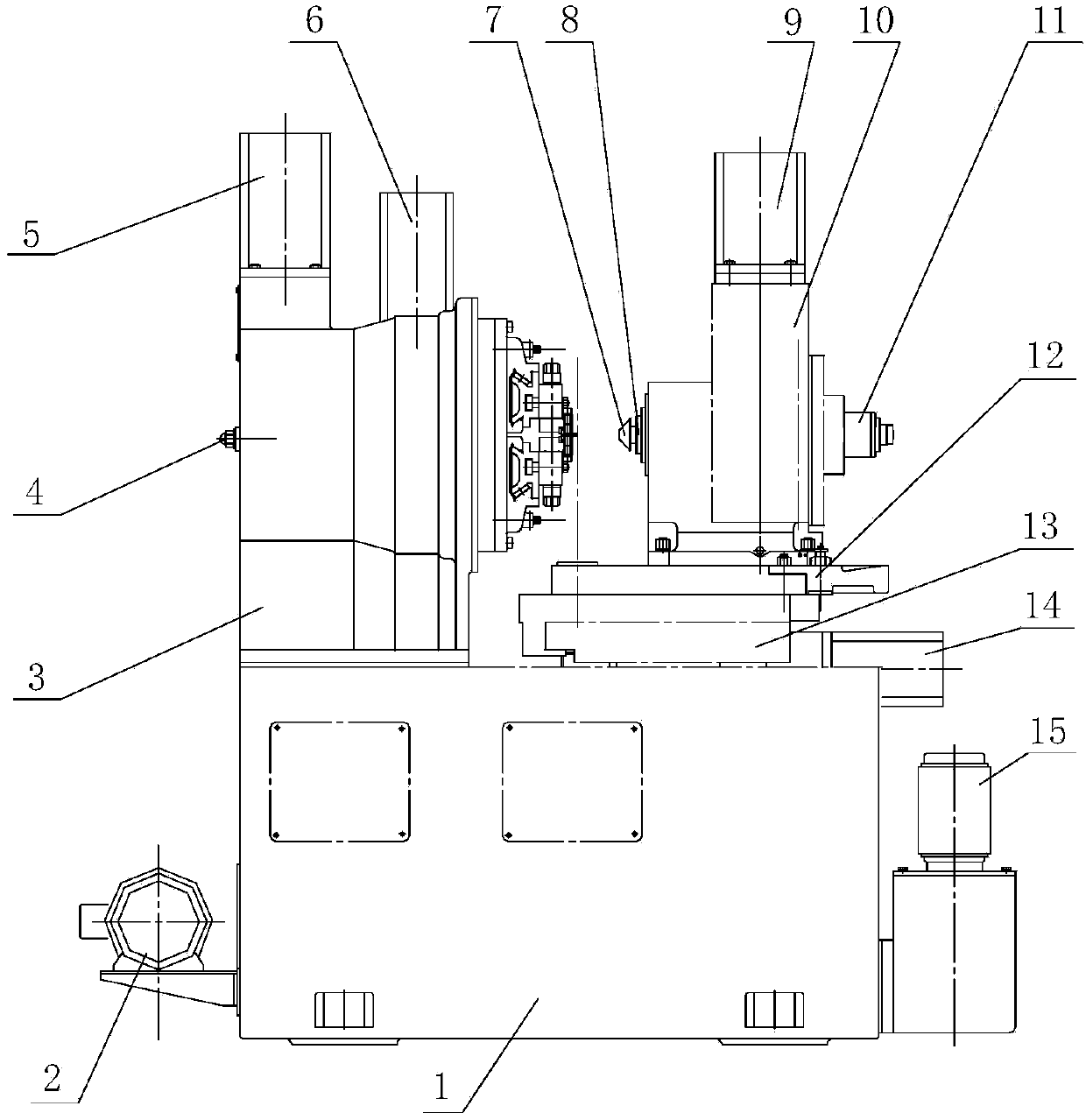
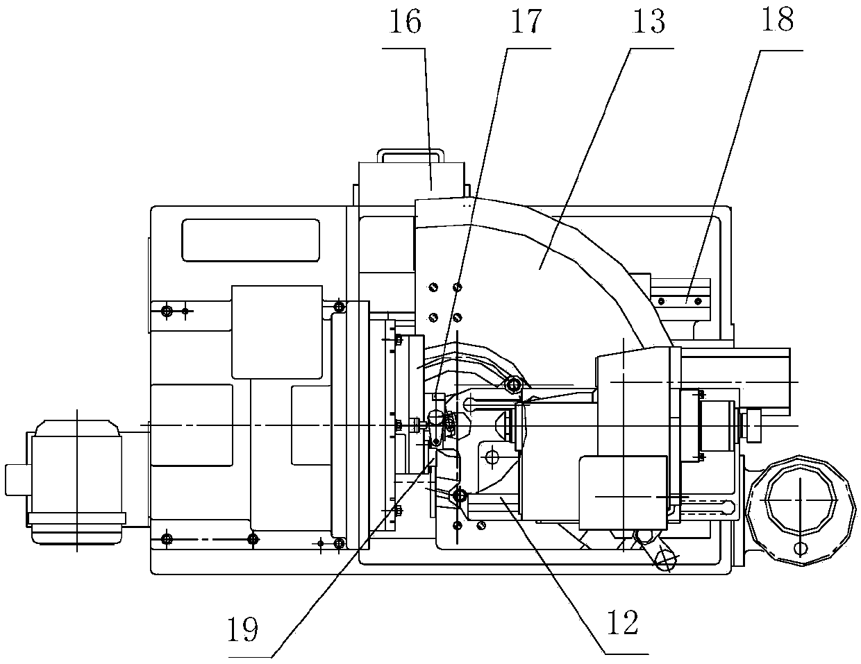
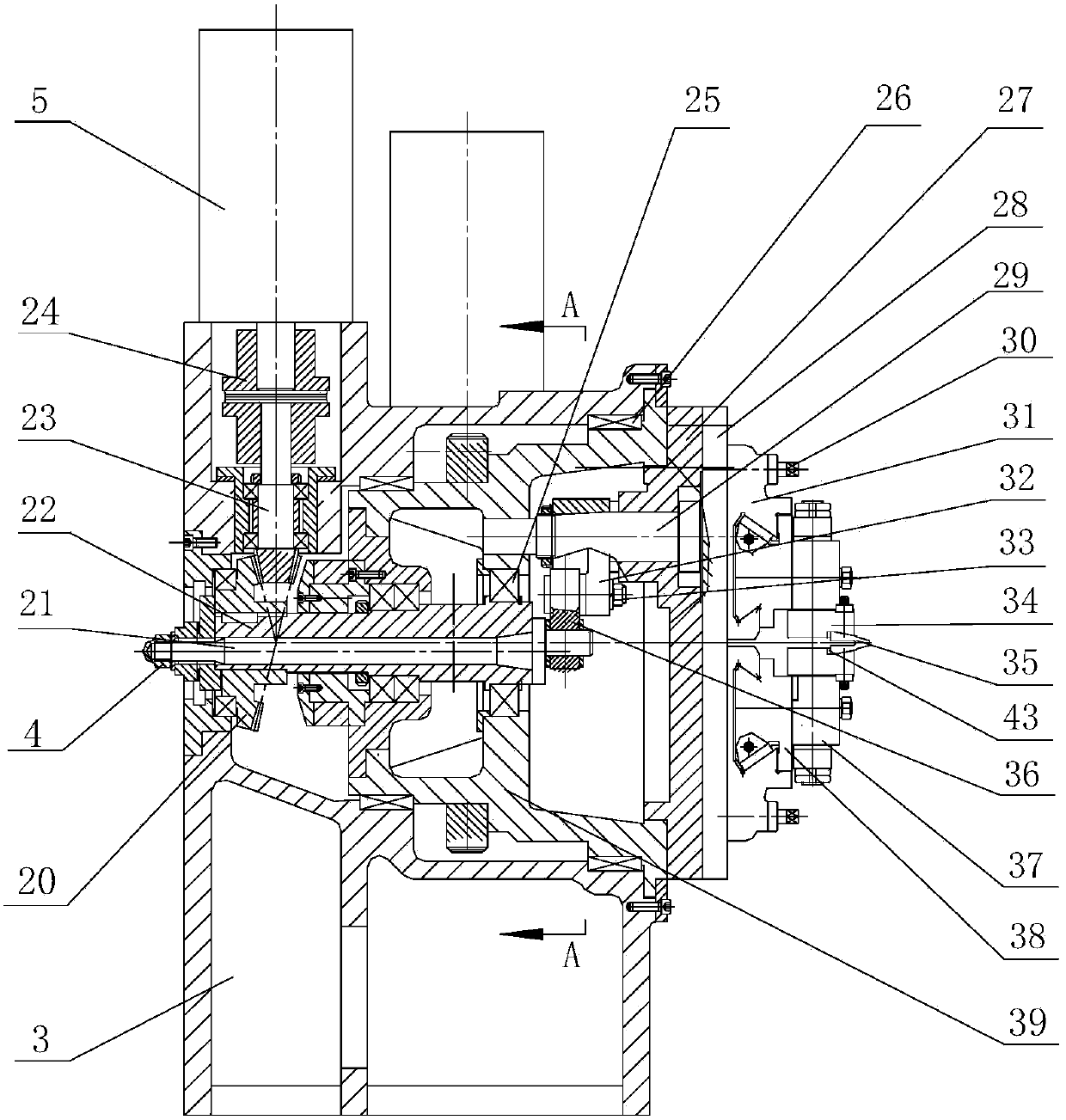
[0036] See figure 1 Figure 13 , CNC small module spur bevel gear planer, including bed 1, cradle assembly, workpiece box assembly, hydraulic system and CNC system, said hydraulic system including lubrication system 2 and cooling system 15, the bed The body is equipped with a rocking table assembly and a workpiece box assembly, and a lubrication system 2, a cooling system 15 and a numerical control system are provided on both sides of the bed. Two guide rails 18, a saddle moving servo motor 14 and a lead screw nut mechanism 42 are installed on the bed 1, and a saddl...


PUM


Abstract

The invention relates to a numerical control small-modulus straight bevel gear shaper comprising a lathe bed, a rocking table assembly, a workpiece box assembly, a hydraulic system and a numerical control system. The lathe bed is provided with the rocking table assembly and the workpiece box assembly; and the hydraulic system is arranged on the two sides of the lathe bed. The rocking table assembly comprises a rocking table support, a tool holder transmission mechanism, a rocking table drum wheel, a tool holder device, a stroke adjusting mechanism, a gear shaping cutter movement main shaft servo motor, a rocking table rotating servo motor and a rocking table rotating worm gear and worm mechanism connected with the rocking table rotating servo motor and is characterized in that the tool holder device comprises a tool holder base, a ram, a tool base support, a tool base, a tool back-off movement adjusting device, a gear angle adjusting mechanism, a gear shaping tool, a tool height adjusting mechanism and a pressure angle adjusting mechanism. The numerical control small-modulus straight bevel gear shaper has the beneficial effects of being compact in structural layout, easy and convenient to adjust and operate, large in tool back-off amount, wide in adjusting range, accurate in tool back-off movement and capable of avoiding the self-locking phenomenon, improving the gear machining precision and meeting the machining requirements of high-precision small-modulus straight bevel gears.

Description

Technical field [0001] The invention belongs to the technical field of gear shaper manufacturing, and particularly relates to a numerically controlled small modulus straight-tooth bevel gear gear shaper. Background technique [0002] Small modulus spur bevel gears are widely used in aerospace, aviation, robot manufacturing and other fields. Small modulus spur bevel gears have good market prospects as parts of small or micro mechanical transmission components and are in great demand. Because the smaller the gear modulus, the more difficult it is to machine, and it is difficult to meet the gear's tooth profile, tooth direction error requirements and machining accuracy. [0003] The tool of the small modulus spur bevel gear shaping machine performs a high-speed reciprocating stroke on the guide rail of the tool rack while completing the tool movement. The so-called knife action is: during the planing work stroke, the planer is lifted and there is enough lifting force to ensure that t...

Claims


Application Information

Patent Timeline
Patent Type & Authority Patents(China)
IPC IPC(8): B23F5/12B23F23/12
CPCB23F5/12B23F23/1237
Inventor 赵巍刘家兰陈义召吴文仲刘洪汉李艳慧邓琼
Owner 通用技术集团天津第一机床有限公司
Why Eureka
Try Eureka