Composite wall adopting fixed-form latent heat storage phase-change material

A composite wall and phase change material technology, applied to walls, climate change adaptation, building components, etc., can solve problems such as waste of manpower and land resources, insufficient wall thickness, and increased wall thickness, so as to improve solar energy utilization efficiency, reducing solar heat loss, and reducing land use

Inactive Publication Date: 2016-09-28
TIANJIN UNIV RES INST OF ARCHITECTRUAL DESIGN & URBAN PLANNING
View PDF5 Cites 4 Cited by
  • Summary
  • Abstract
  • Description
  • Claims
  • Application Information

AI Technical Summary

Problems solved by technology

There is no basis for the selection of wall thickness during the construction process. When low-temperature freezing damage occurs in the greenhouse, it is subjectively believed that the wall is not thick enough and the heat energy accumulation is insufficient during the day. There is a phenomenon of blindly increasing the wall thickness, which not only lacks scientific basis , but also waste a lot of manpower and land resources
[0004] (2) Traditional wall materials limit the use of solar energy by greenhouse walls
The structure of the traditional greenhouse is simple, and the thermal storage performance and thermal insulation performance are generally poor. When the outdoor air temperature drops, energy is released on both sides of the wall, and the temperature conditions for the normal growth of crops cannot be guaranteed.
Therefore, heating is often required in winter, conventional energy consumption is relatively large, and solar energy has not been effectively utilized.

Method used


Image

  • Composite wall adopting fixed-form latent heat storage phase-change material
  • Composite wall adopting fixed-form latent heat storage phase-change material
  • Composite wall adopting fixed-form latent heat storage phase-change material

Examples


Embodiment Construction

[0017] The specific implementation of the present invention will be described in detail below in conjunction with preferred embodiments.

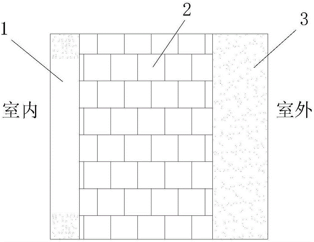
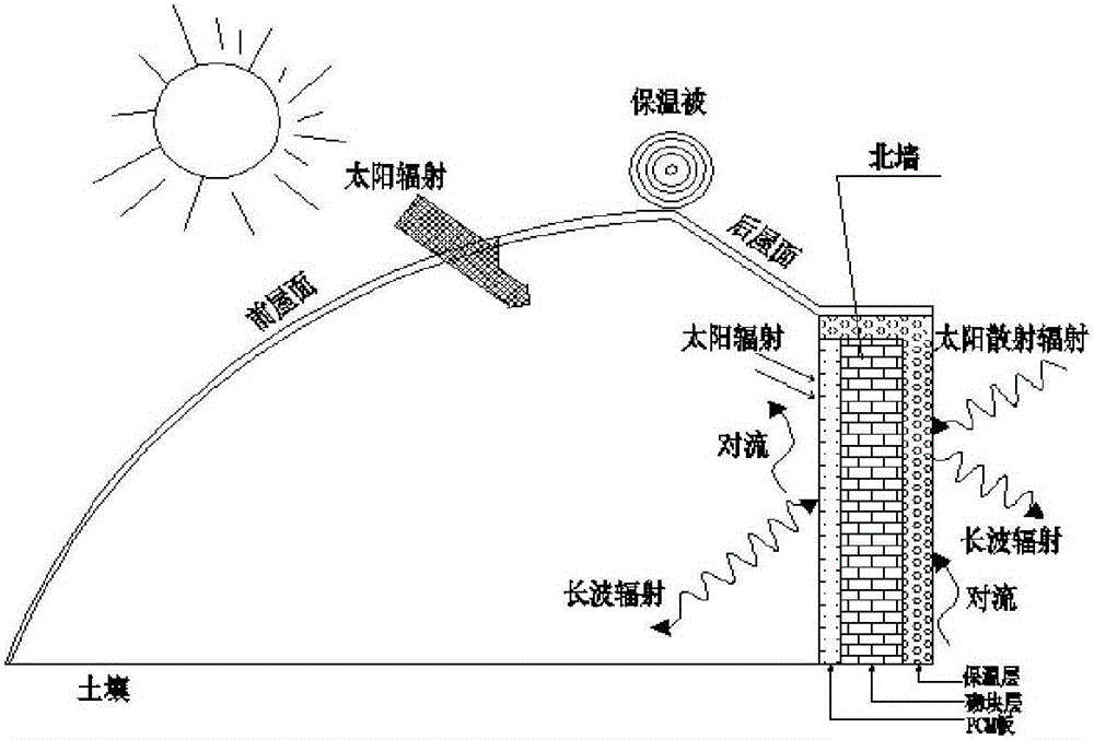
[0018] see attached figure 1 , 2 , this example provides a composite wall using a shaped latent heat storage phase change material, including a wall, the wall includes a phase change heat storage layer, a block layer and an insulation layer connected in sequence from the inside to the outside to form three layers In the structural phase change composite wall, the phase change heat storage layer is placed on the inner side of the north wall, the insulation layer is placed on the outermost side of the north wall, and the block layer is placed between the phase change heat storage layer and the heat preservation layer. The thickness of the phase change thermal storage layer is 10-100mm; the thickness of the block layer is 250-500mm; the thickness of the heat preservation layer is 40-60mm.

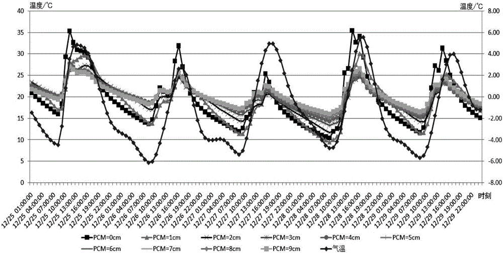
[0019] The optimal thickness of the three-layer str...


PUM

PropertyMeasurementUnit
thicknessaaaaaaaaaa
thicknessaaaaaaaaaa
thicknessaaaaaaaaaa

Abstract

The invention relates to a composite wall adopting a fixed-form latent heat storage phase-change material. The composite wall comprises a wall body and is characterized in that the wall body comprises a phase-change heat storage layer, a building block layer and a heat insulation layer which are connected from inside to outside sequentially and form a phase-change composite wall body with a three-layer structure, the phase-change heat storage layer is arranged on the inner side of a north wall, the heat insulation layer is arranged on the outermost side of the north wall, and the building block layer is arranged between the phase-change heat storage layer and the heat insulation layer. The composite wall has the beneficial effects as follows: the phase-change material utilizing glass bead particles as main components is adopted and can store or release a large amount of latent heat during heat storing or releasing, and by means of phase-change temperature of high heat storage and low heat release, the composite wall is enabled to show an obvious peak load shifting function, particularly has a remarkable effect for increase of night temperature and guarantees a thermal environment in a greenhouse; the heat storage capability of an inner surface material layer of a greenhouse wall is improved, solar heat power projected on the inner surface material layer is sufficiently absorbed and stored in a period of effective sunlight, and the utilization ratio of solar energy is increased.

Description

technical field [0001] The invention belongs to the technical field of facility agricultural engineering, and in particular relates to a composite wall body which adopts shape-setting latent heat storage phase change materials and is suitable for application in greenhouses. Background technique [0002] The use of solar energy in greenhouses can provide a suitable microclimate environment for plant growth. It has the advantages of not being limited by seasons or regions, over-seasonal production and improving land utilization. In recent years, based on its advantages of low building operation cost, simple structure and convenient management, plastic greenhouses have been favored by more farmers and have achieved faster and better development in facility agriculture. The plastic greenhouse is a relatively closed hot and humid environment established by covering film and enclosure structure. As an enclosure structure, the north wall carries multiple functions such as heat col...

Claims


Application Information

Patent Timeline
Patent Type & Authority Applications(China)
IPC IPC(8): E04B2/00E04B1/76A01G9/14
CPCA01G9/14E04B1/7675E04B2/00E04B2002/0286Y02A40/25Y02P60/12
Inventor 宋晓帆
Owner TIANJIN UNIV RES INST OF ARCHITECTRUAL DESIGN & URBAN PLANNING
Why Eureka
Try Eureka