Measurement method for time delay test of quadrature phase shift keying modulator

A technology of quadrature phase shift keying and measurement method, which is applied in transmission monitoring, electrical components, transmission systems, etc., can solve the problems of difficulty in locating the phase reversal point, small amplitude of modulation waveform envelope, measurement error, etc., and achieves the measurement method. Simple and easy, fast real-time response, high measurement accuracy

Inactive Publication Date: 2016-09-28
UNIT 63680 OF PLA
View PDF5 Cites 11 Cited by
  • Summary
  • Abstract
  • Description
  • Claims
  • Application Information

AI Technical Summary

Problems solved by technology

[0003] The delay test can generally be divided into carrier measurement method and modulation measurement method, in which the carrier measurement method accurately measures the phase difference of the input and output carrier signals of the system under test, and estimates the signal delay according to the phase difference; the modulation measurement method is to modulate the carrier Finally, through the device under test, the signal is demodulated at the output end and the time delay is estimated by comparing it with the reference signal, but there is a problem that the maximum unambiguous distance and the ranging accuracy are contradictory, and the spread spectrum pseudo-code ranging is the problem. A solution is provided, which has obvious advantages over the sidetone ranging system in terms of measurement range and measurement accuracy, but none of the above methods can directly measure the delay of a general quadrature modulator
[0004] The delay of the quadrature modulator is defined as the time delay from the transition point of the input baseband pseudocode signal rising to 50% of the highest average level to the output RF phase inversion point corresponding to the transition, but there are still The following uncertain factors: one is the uncertainty of the transition edge of the input baseband pseudocode. The input baseband pseudocode signal contains two waveform signals of I and Q. Since the position of the output RF phase inversion point is related to the two input signals at the same time, the two The time synchronization error of the input signal jump edge will introduce measurement error; the second is the uncertainty of the output RF phase inversion point. In order to overcome the intersymbol interference, the input baseband signal will be band-limited preprocessing, resulting in the modulator output RF phase inversion point The amplitude of the modulated waveform envelope at any moment is the smallest, which makes it difficult to locate the phase inversion point

Method used


Image

  • Measurement method for time delay test of quadrature phase shift keying modulator
  • Measurement method for time delay test of quadrature phase shift keying modulator
  • Measurement method for time delay test of quadrature phase shift keying modulator

Examples


Embodiment Construction

[0032] The present invention will be further described in detail below in conjunction with the accompanying drawings and embodiments.

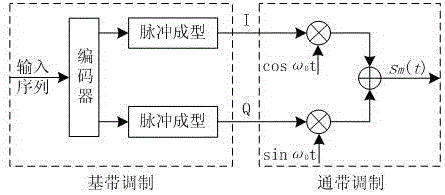
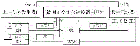
[0033] Such as figure 1 , as shown in 2, a measurement method for the delay test of a quadrature phase shift keying modulator in the present embodiment, before performing the measurement, a measurement model shall be established for the delay of the modulator, and then the measurement of the delay of the modulator shall be carried out

[0034] Quadrature phase shift keying modulator delay measurement model, including the following steps:

[0035] Step 1: Determine the input volume and output volume according to the working principle

[0036] The working principle of quadrature phase shift keying modulator is as follows: figure 1 As shown in the passband modulation part, according to its input and output relationship, the input I and Q baseband signals are defined as and , the envelope waveform of the output modulation signal .

[0037...


PUM


Abstract

The invention relates to a measurement method for a time delay test of a quadrature phase shift keying modulator. A relation formula, meeting the requirements of time delay measurement, of input and output of the quadrature phase shift keying modulator is given, and a time delay measurement model is built through the principle of maximum likelihood estimation. Based on the above, a time delay test system formed based on a digital oscilloscope and a baseband signal and a measurement method for the time delay test are given, and the error components caused by the manual interpretation of the jump edges of input and output signals are eliminated. When a measurement main regulator digital oscilloscope carries out signal collection at a sampling rate of 25GS/s, the uncertainty of a time delay measurement result is not less than 100ps. The system is high in measurement accuracy, is simple and feasible in measurement method, is relatively low in requirements for hardware, is high in real-time response, and can be used for the link time delay calibration of a high-precision satellite measurement and control and navigation positioning system.

Description

technical field [0001] The invention relates to a method for measuring the time delay of a modulator, in particular to a method for measuring the time delay of a quadrature phase shift keying modulator. Background technique [0002] With the continuous development of science and technology, in many fields such as aerospace measurement and control, satellite navigation, and inter-satellite radio measurement, the measurement accuracy of distance and long-distance time difference is getting higher and higher. However, since the modulator, frequency converter, power amplifier, low-noise amplifier and other equipment that make up the transceiver of the ranging system are nonlinear phase systems, group delay fluctuations and phase distortions will occur when the ranging signal passes through these non-ideal transmission channels; at the same time Uncertain error factors such as noise interference, multipath influence, impedance mismatch, and temperature drift that are ubiquitous i...

Claims


Application Information

Patent Timeline
Patent Type & Authority Applications(China)
IPC IPC(8): H04B17/364
CPCH04B17/364
Inventor 夏伟沈小青丁风海邱斌孙朝斌余清华王琳娜
Owner UNIT 63680 OF PLA
Why Eureka
Try Eureka