
Magnetorheological fluid recycling device and treatment method based on temperature variation, ionization and centrifugation effects

A technology of magnetorheological fluid and centrifugation, applied in centrifugal separation of water/sewage treatment, chemical instruments and methods, electrochemical water/sewage treatment, etc., can solve problems such as energy waste, environmental pollution, and difficulties in magnetorheological fluid , to achieve the effect of reducing the volume of the equipment, improving the structural strength, and not easy to settle

Inactive Publication Date: 2016-10-12
MAANSHAN FULAIYI ENVIRONMENT PROTECTION TECH CO LTD
View PDF2 Cites 0 Cited by
  • Summary
  • Abstract
  • Description
  • Claims
  • Application Information

AI Technical Summary

Problems solved by technology

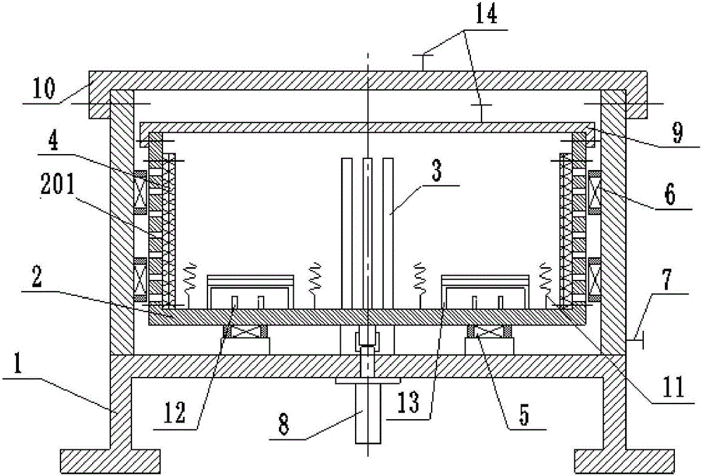
[0009] Aiming at the problem that the existing discarded magnetorheological fluid is difficult to recycle, and directly discarded causes environmental pollution and energy waste, the present invention provides a magnetorheological fluid recovery device and treatment method based on temperature change, ionization and centrifugal action, The magnetorheological fluid can be recovered through temperature change and centrifugation, and the main dispersed particles and carrier liquid can be separated and recovered. There is no need for any treatment agent for preliminary treatment in the early stage, and the recovery efficiency of magnetic substances is high. At the same time, no new substances are introduced in the treatment. , the recovered carrier liquid can be used as a new carrier liquid after a little treatment

Method used


Image

  • Magnetorheological fluid recycling device and treatment method based on temperature variation, ionization and centrifugation effects

Examples


Embodiment 1

[0053] like figure 1 As shown, a magnetorheological fluid recovery device based on temperature change, ionization and centrifugation in this embodiment includes an outer barrel 1 , an inner barrel 2 , an adsorption tube 3 and a filter 4 . Wherein, the inner barrel body 2 is installed in the outer barrel body 1 through bearing rotation, specifically in this embodiment, the bottom of the inner barrel body 2 and the outer barrel body 1 are supported and connected by a thrust bearing 5, and the outer side wall of the inner barrel body 2 A lateral bearing is installed between the inner wall of the outer barrel body 1, the thrust bearing 5 supports the rotation of the inner barrel body 2, and the lateral bearing ensures the rotation stability of the inner barrel body 2, effectively reducing the damage caused by uneven force and vibration of the inner barrel body 2. The resulting vibration and noise of the whole machine also improves the structural strength of the whole machine. The...

Embodiment 2

[0060] This embodiment provides a method for reclaiming and treating magnetorheological fluid. The device in Embodiment 1 is used to process the waste magnetorheological fluid, and the diameter of the filter hole 201 is specifically limited to 2 mm, and the mesh number of the filter screen 4 is 2400 mesh. The area of ​​electrode plate 13 is 80cm 2 , The spacing between positive and negative plates is 10mm. The magnetorheological fluid to be treated is a magnetorheological fluid with oleic acid as the main component of the surfactant, the main dispersed particles are hydroxyl iron powder, the magnetic saturation is 2.5T, and the carrier liquid is dimethyl silicone oil; and this embodiment The magnetorheological fluid waste to be treated is the solution after its use exceeds its shear fatigue life. At this time, the variation of its zero-shear viscosity and adjustable multiple exceeds ±10% during the inspection process. The specific operation steps are as follows:

[0061] Ste...

Embodiment 3

[0087] This embodiment provides a method for reclaiming and treating magnetorheological fluid. The device in Example 1 is used to process the waste magnetorheological fluid, and the diameter of the filter hole 201 is specifically limited to 5 mm, and the mesh number of the filter screen 4 is 2450 mesh. The area of ​​electrode plate 13 is 90cm 2 , The spacing between positive and negative plates is 14mm. The magnetorheological fluid to be treated is a magnetorheological fluid with oleic acid as the main component of the surfactant, the main dispersed particles are hydroxyl iron powder, the magnetic saturation is 2.7T, and the carrier liquid is dimethyl silicone oil; and this embodiment The magnetorheological fluid waste to be treated is the solution after its use exceeds its shear fatigue life. At this time, the variation of its zero-shear viscosity and adjustable multiple exceeds ±10% during the inspection process. The specific operation steps are as follows:

[0088] Step 1...


PUM


Abstract

The invention discloses a magnetorheological fluid recovery device and treatment method based on temperature change, ionization and centrifugal action, and belongs to the technical field of magnetic waste fluid recovery and treatment. The device includes an outer barrel body, an inner barrel body, an adsorption tube and a filter screen. The inner barrel body is installed in the outer barrel body through bearing rotation and driven by a motor. Filter holes are arranged on the side wall of the inner barrel body, and the adsorption tube is arranged in the inner barrel body. A coil is arranged, a heating resistor, a cooling pipe and an electrode plate are arranged in the inner barrel, a filter screen is arranged on the inner wall of the inner barrel and covers the filter hole, and a recovery shut-off valve is arranged on the outer wall of the outer barrel. The method of the invention realizes the separation and recovery treatment of the magnetorheological fluid through temperature change treatment, centrifugal breaking and separation treatment. The invention treats the magnetorheological fluid, separates and recovers the main dispersed particles and the carrier liquid, does not need any treatment agent for preliminary treatment in the early stage, has high recovery efficiency, and at the same time, the recovered carrier liquid can be used as a new carrier liquid after a little treatment.

Description

technical field [0001] The invention belongs to the technical field of recovery and treatment of magnetic waste liquid, and more specifically relates to a magnetorheological fluid recovery device and treatment method based on temperature change, ionization and centrifugal action. Background technique [0002] Magnetorheological Fluid (MR fluid for short) is a controllable fluid, which is an emerging intelligent material. It is mainly composed of magnetic particles, carrier liquid and stabilizer. Suspension liquids with characteristic non-colloidal properties. Magnetorheological fluid can produce obvious magnetorheological effect under a magnetic field, and can realize rapid and reversible conversion between liquid and solid or semi-solid. During this process, the viscosity of magnetorheological fluid keeps changing continuously, and the entire conversion process is extremely fast. And controllable, has the characteristics of extremely small energy consumption, convenient pr...

Claims


Application Information

Patent Timeline
IPC IPC(8): C02F9/12H01F1/44
CPCC02F9/00C02F1/02C02F1/38C02F1/46C02F1/484C02F2301/08H01F1/447
Inventor 邢战伟赵奎刘鹏
Owner MAANSHAN FULAIYI ENVIRONMENT PROTECTION TECH CO LTD
Learn More