
A method and equipment for preparing ultra-low loss optical fiber preform rod with pure silicon core cladding doped with fluorine

An optical fiber preform and core-packing technology, which is applied in glass manufacturing equipment, manufacturing tools, glass deposition furnaces, etc., can solve problems such as unfavorable refractive index profile, unfavorable loose body dehydration, and high water peak of optical fiber

Active Publication Date: 2019-02-15
ZHONGTIAN TECH ADVANCED MATERIALS CO LTD +1
View PDF9 Cites 0 Cited by
  • Summary
  • Abstract
  • Description
  • Claims
  • Application Information

AI Technical Summary

Problems solved by technology

However, in actual production, due to the structure of the dense layer, if the density is high, it is not conducive to the dehydration of the loose body, resulting in a high water peak in the optical fiber; if the density is low, the doped fluorine element still penetrates into the core layer, which is not conducive to the formation of stages refractive index profile
If the pure silicon core rod and the F-doped cladding sleeve are separately produced and re-melted in the manufacturing process, the complexity of the process will also be greatly increased.

Method used


Image

  • A method and equipment for preparing ultra-low loss optical fiber preform rod with pure silicon core cladding doped with fluorine
  • A method and equipment for preparing ultra-low loss optical fiber preform rod with pure silicon core cladding doped with fluorine
  • A method and equipment for preparing ultra-low loss optical fiber preform rod with pure silicon core cladding doped with fluorine

Examples


Embodiment 1

[0062] Example 1: Manufacturing Φ200mm×1600mm pure silicon core cladding fluorine-doped ultra-low loss optical fiber preform

[0063] (1) Use quartz glass material as the deposition target. The selected target rod is pickled, soaked in 10% hydrochloric acid for 1 hour to remove impurities attached to the surface of the target rod, then rinsed repeatedly with deionized water, and finally dried.

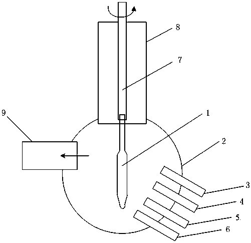
[0064] (2) Clamp the pre-processed target rod on the hanger of the VAD equipment. Using silicon tetrachloride, oxygen, carbon monoxide, helium and nitrogen mixture as raw material gas, the flow rate of each raw material gas is 5g / min, 7.5L / min, 5L / min, 5L / min, 1.5L / min, After entering the quartz core layer torch, the silicon dioxide particles generated by the high-temperature reaction of the raw material in the flame are deposited on the surface of the target rod perpendicular to the torch. Above the core layer, two auxiliary blowtorches are arranged perpendicular to each other, and carbo...

Embodiment 2

[0067] Example 2: Manufacturing Φ200mm×1600mm pure silicon core cladding fluorine-doped ultra-low loss optical fiber preform

[0068] (1) Use quartz glass material as the deposition target. The selected target rod is pickled and soaked in 10% hydrochloric acid for 1.5 hours to remove impurities attached to the surface of the target rod, then rinsed repeatedly with deionized water, and finally dried.

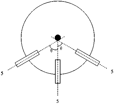
[0069] (2) Clamp the pre-processed target rod on the hanger of the VAD equipment. Using silicon tetrachloride, oxygen, carbon monoxide, helium and nitrogen mixture as raw materials, the flow rates of each raw material gas are 5g / min, 11.3L / min, 10L / min, 5L / min, 2L / min, and pass in After the quartz core layer torch, the silicon dioxide particles generated by the high-temperature reaction of the raw material in the flame are deposited on the surface of the target rod perpendicular to the torch. Above the core layer, three auxiliary blowtorches are arranged with a value of 120°. Carbon...

Embodiment 3

[0072] Example 3: Manufacturing Φ200mm×1600mm pure silicon core cladding fluorine-doped ultra-low loss optical fiber preform

[0073] (1) Use quartz glass material as the deposition target. The selected target rod is pickled, soaked in 10% hydrochloric acid for 2 hours to remove impurities attached to the surface of the target rod, then rinsed repeatedly with deionized water, and finally dried.

[0074] (2) Clamp the pre-processed target rod on the hanger of the VAD equipment. Using silicon tetrachloride, oxygen, carbon monoxide, helium and nitrogen mixture as raw materials, the flow rates of various raw materials are 5g / min, 15L / min, 15L / min, 5L / min, 2.5L / min, and pass through After the quartz core layer torch, the silicon dioxide particles generated by the high-temperature reaction of the raw material in the flame are deposited on the surface of the target rod perpendicular to the torch. Above the core layer, there are 5 auxiliary blowtorches with a Ɵ of 72°. Each blowtorch is ...


PUM


Abstract

The invention discloses a method and equipment for preparing an ultralow-loss optical fiber perform with a fluorine-doped pure silicon core cladding, and relates to a method for preparing the ultralow-loss optical fiber perform with the fluorine-doped pure silicon core cladding by doping fluorine in the cladding through powder obtained according to a vapor deposition method. The equipment comprises a target bar, a deposition chamber, an outer-cladding blow lamp, a middle-cladding blow lamp, an auxiliary blow lamp, a core layer blow lamp, a suspension rod, an exhaust pipe, an upper deposition cavity and a graphite heating resistance furnace. The upper deposition cavity is formed in the upper portion of the deposition chamber. The suspension rod is mounted in the upper deposition cavity, is provided with a hook and is connected with a lifting mechanism. The target bar is hung on the hook of the suspension rod connected with the lifting mechanism. The outer-cladding blow lamp, the middle-cladding blow lamp, the auxiliary blow lamp and the core layer blow lamp are mounted on one side of the lower portion of the disposition chamber sequentially. A graphite sintering furnace comprises a quartz suspension rod, a sealing component, a cover plate, a quartz furnace core tube, a graphite furnace core tube, a gas pipeline, a target bar, a powder body, a graphite heating body and a gas quality and flow controller.

Description

Technical field [0001] The invention relates to a method and equipment for preparing a pure silicon core cladding fluorine-doped ultra-low loss optical fiber preform, which relates to a powder obtained by a vapor deposition method, and fluorine is doped in the cladding to prepare a pure silicon core A method of cladding fluorine-doped ultra-low loss optical fiber preform. Background technique [0002] The optical fiber preform is the raw material for optical fiber manufacturing, which usually consists of a core layer and a cladding layer composed of materials with different refractive indexes. Silica is the main matrix material for the manufacture of optical fiber preforms. The refractive index of the core layer is increased by doping germanium in the core layer n core , Making the refractive index of the core layer greater than that of the pure silicon cladding layer n sio2 , So as to meet the total reflection condition of fiber transmission, that is, to reach a certain core-pa...

Claims


Application Information

Patent Timeline
Patent Type & Authority Patents(China)
IPC IPC(8): C03B37/014
CPCC03B37/01453C03B2207/28C03B2207/38C03B2207/50
Inventor 吴椿烽沈一春钱宜刚
Owner ZHONGTIAN TECH ADVANCED MATERIALS CO LTD
Learn More