Inert gas shielding immersion type heating difunctional low-pressure casting furnace

An inert gas, low pressure casting technology, applied in the field of low pressure casting, can solve problems such as affecting production continuity, increasing power consumption, increasing hydrogen and oxygen content, etc., achieving excellent thermal shock resistance, avoiding the introduction of impurities, excellent electrical insulating effect

Inactive Publication Date: 2016-10-26
LIAONING YIFEI TECH +1
View PDF9 Cites 9 Cited by
  • Summary
  • Abstract
  • Description
  • Claims
  • Application Information

AI Technical Summary

Problems solved by technology

The holding furnace has the following problems in the application process: 1. It affects the continuity of production. When adding aluminum liquid, the heating power supply must be cut off to stop production; 2. The heating of silicon carbide rods is radiant heating, and the heating efficiency is low. The increase of surface oxides will increase the generation of slag inclusion waste products; 3. The heating life of silicon carbide rods is short, generally 1 to 2 months is the replacement period, resulting in reduced labor costs and work efficiency
4. The lining material of the molten aluminum pool of the general low-pressure casting holding furnace is made of traditional castables, which are easy to produce polymers at high temperatures. With the prolongation of production time, the space of the molten aluminum pool becomes smaller and the melt is clean. 5. The original pressurization method is compressed air, and the furnace is filled and discharged with compressed air, which will take away a lot of heat and increase the consumption of electric energy; 6. .The compressed gas is air, which increases the amount of hydrogen and oxygen in the molten aluminum, and the castings are prone to pinholes, resulting in an increase in unqualified products

Method used


Image

  • Inert gas shielding immersion type heating difunctional low-pressure casting furnace
  • Inert gas shielding immersion type heating difunctional low-pressure casting furnace
  • Inert gas shielding immersion type heating difunctional low-pressure casting furnace

Examples


Embodiment Construction

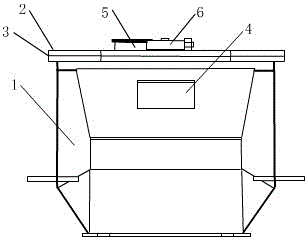
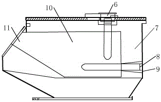
[0020] As shown in the figure, a furnace cover 2 is installed on the upper part of the furnace shell 1 through a cover seal 3, and the furnace door 4 is located at the upper right side of the furnace shell. The heater 6 is also inserted into the aluminum melting pool from the upper part of the furnace cover, and the aluminum melting pool lining 7 is arranged between the outer side of the aluminum melting pool and the furnace shell;

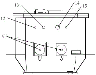
[0021] Two immersion heaters 8 are installed in the aluminum melting pool in the furnace shell through YF cement seal 9, and a PID temperature control component 16 is installed between the two immersion heaters;

[0022] The upper edge of the rear part of the furnace shell is provided with an air inlet 12, an air outlet 15, a pressure sensor interface 13, and a thermocouple interface 14;

[0023] Furnace door replenishment 11 is provided on the front side of the furnace door;

[0024] The inner lining of the molten aluminum pool is composed of hi...


PUM


Abstract

The invention provides an inert gas protection immersion heating dual-function low-pressure casting furnace. The lining of the molten aluminum pool is composed of high-nitrogen composite ceramic bricks, light heat insulation layer, heat insulation material and thermal insulation composite material; plug-in heaters and immersion heaters are made of silicon nitride ceramic tubes with built-in resistance wires. Heating elements; the plug-in heater is inserted into the molten aluminum pool from the upper end of the furnace cover, and the immersion heater is directly immersed in the molten aluminum pool from the outside of the furnace shell to achieve double heating; the air inlet is connected to the compressed preheating inert gas generator, The gas outlet is connected to the gas recovery device; the riser pipe and the plug-in heater are immersed in the molten aluminum, and two immersion heaters are installed at the bottom of the aluminum melting pool, and the lower end of the riser pipe is higher than the bottom immersion heater. The invention has uniform heating rate, high thermal efficiency, low energy consumption, good thermal shock resistance and cost saving. It is suitable for use as an aluminum alloy casting furnace.

Description

technical field [0001] The invention belongs to the technical field of low-pressure casting, in particular to an inert gas-protected immersion heating double-function low-pressure casting furnace. Background technique [0002] The general-purpose low-pressure casting holding furnace is generally heated by silicon carbide rod radiation, and the heat heats the molten aluminum in the furnace through radiation and air conduction. The holding furnace has the following problems in the application process: 1. It affects the continuity of production. When adding aluminum liquid, the heating power supply must be cut off to stop production; 2. The heating of silicon carbide rods is radiant heating, and the heating efficiency is low. The increase of surface oxides will increase the generation of slag inclusion waste products; 3. The heating life of silicon carbide rods is short, generally 1 to 2 months is the replacement period, resulting in reduced labor costs and work efficiency. 4....

Claims


Application Information

Patent Timeline
Patent Type & Authority Applications(China)
IPC IPC(8): B22D18/04
CPCB22D18/04
Inventor 常艳杰倪世军田鑫蒋威奚克波李季
Owner LIAONING YIFEI TECH
Why Eureka
Try Eureka