Distributed Bragg reflection laser-based chirp microwave generating device

A microwave generating device and distributed Bragg technology, applied in the microwave field, can solve problems such as low time-bandwidth product and compression, deterioration of radar performance, narrow center frequency tuning range, etc., and achieve high time-bandwidth product and compression ratio, flexible bandwidth and period , the effect of high power flatness

Inactive Publication Date: 2016-11-02
INST OF SEMICONDUCTORS - CHINESE ACAD OF SCI
View PDF7 Cites 1 Cited by
  • Summary
  • Abstract
  • Description
  • Claims
  • Application Information

AI Technical Summary

Problems solved by technology

The University of Ottawa proposed a variety of chirped microwave generation methods based on frequency-time mapping (ChaoWang and Jianping Yao, IEEE transactions on Microwave Theory and Techniques, 2008, 56(2): 542-553; Chao Wang and Jianping Yao, IEEE Photonics Technology Letters ,2008,20(11):882-884), the common disadvantages of this kind of methods are narrow center frequency tuning range, low time-bandwidth product and compression ratio
Jin-Wei Shi et al. from Taiwan, China proposed a scheme to obtain chirped microwaves by using DC light and fast frequency-sweeping distributed feedback (DFB) laser beating frequency (J.-W.Shi, F.-M.Kuo, et al., IEEE Photonics Journal, 2012, 4(1): 215-223; Jhih-Min Wun, Chia-Chien Wei, et al., Optics Express, 2013, 21(9): 11475-11481), this scheme can be compared With high time-bandwidth product and compression ratio, the shape of chirped microwaves can also be adjusted well. However, the principle of fast frequency sweep is based on thermal effects, so the tuning speed is slow, and the frequency of chirped microwaves can only be adjusted to the order of 10kHz. High frequency will be at the cost of reduced bandwidth, and the obtained chirped microwave flatness is poor, which will directly deteriorate the performance of the radar

Method used


Image

  • Distributed Bragg reflection laser-based chirp microwave generating device
  • Distributed Bragg reflection laser-based chirp microwave generating device
  • Distributed Bragg reflection laser-based chirp microwave generating device

Examples


Embodiment 1

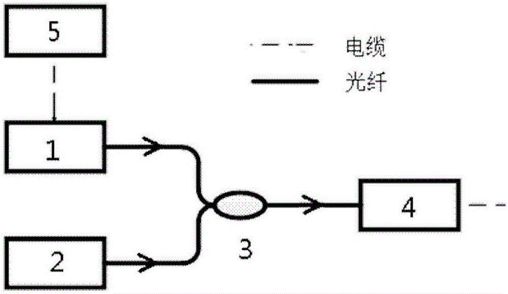
[0036] This embodiment provides a chirped microwave generation device based on a distributed Bragg reflection laser, such as figure 1 As shown, the chirped microwave generating device includes a distributed Bragg reflection laser 1 , a tunable single-mode laser 2 , an optical coupler 3 , a photodetector 4 and an arbitrary waveform generator 5 .

[0037] Arbitrary waveform generator 5 and distributed Bragg reflection laser 1 adopt cable connection, provide electrical signal for distributed Bragg reflection laser 1, can be voltage signal or current signal, preferably voltage signal, thereby change the lasing wavelength of distributed Bragg reflection laser 1 , so that the laser output from the distributed Bragg reflection laser 1 has a specific chirp.

[0038] Both the distributed Bragg reflection laser 1 and the tunable single-mode laser 2 are connected to the optical coupler 3 by optical fiber, and the laser with a specific chirp output by the distributed Bragg reflection lase...

Embodiment 2

[0046] This embodiment provides a chirped microwave generation device based on a distributed Bragg reflection laser, such as Figure 4 As shown, compared with Embodiment 1, the only difference is that an optical isolator 6 is added between the distributed Bragg reflection laser 1 and the optical coupler 3 to avoid adverse effects caused by the optical feedback at the optical coupler 3 back to the distributed Bragg reflection laser 1 .

[0047] In this embodiment, the chirped laser output by the distributed Bragg reflection laser 1 is transmitted to the optical isolator 6 through the optical fiber, and then transmitted to the optical coupler 3 and coupled with the single-mode laser output by the tunable single-mode laser 2 through the optical fiber, and the coupled laser It is transmitted to the photodetector 4 through the optical fiber, and the photodetector 4 converts the beat frequency signal of the coupled laser into an electrical signal, and outputs chirped microwaves to t...


PUM


Abstract

The invention provides a distributed Bragg reflection laser-based chirp microwave generating device, which comprises an arbitrary waveform generator used for providing an electric signal which is changed along with the time; a distributed Bragg reflection laser electrically connected with the arbitrary waveform generator and used for generating a chirp laser according to the electric signal which is changed along with the time; a tunable single-mode laser used for generating a tunable single-mode laser; a coupler connected with the distributed Brag reflection laser and the tunable single-mode laser and used for coupling the chirp laser generated by the distributed Bragg reflection laser to the tunable single-mode laser generated by the tunable single-mode laser; and a photoelectric detector used for receiving the coupled laser and then generating a chirp microwave. The chirp microwave generating device can generate chirp microwaves adjustable in shape, period and bandwidth, and super-high in time-bandwidth product and compression ratio.

Description

technical field [0001] The invention belongs to the field of microwave technology, in particular to a chirped microwave generating device based on a distributed Bragg reflection laser. Background technique [0002] Compared with the traditional radar, the new pulse compression radar can greatly improve the distance resolution under the premise of ensuring the detection distance. Broadband chirped microwave signal source, as the core device for transmitting signals, has important research value. At present, chirped microwave signals are generally generated based on electronic methods. However, limited by electronic bottlenecks, it is difficult to obtain broadband chirped microwave signals with a bandwidth exceeding 10 GHz. The photonics-based method has more advantages in terms of bandwidth, tuning performance, and anti-electromagnetic interference. [0003] The methods based on photonics mainly include frequency-time mapping method, beat frequency method and method based o...

Claims


Application Information

Patent Timeline
Patent Type & Authority Applications(China)
IPC IPC(8): H01S1/02
CPCH01S1/02
Inventor 郭露张瑞康陆丹赵玲娟王圩
Owner INST OF SEMICONDUCTORS - CHINESE ACAD OF SCI
Why Eureka
Try Eureka