Eureka AIR delivers breakthrough ideas for toughest innovation challenges, trusted by R&D personnel around the world.

Linear pixel confining layer structure and preparation method thereof

A pixel-defining layer and pixel-defining technology, applied in semiconductor/solid-state device manufacturing, electrical components, electrical solid-state devices, etc., can solve the problems of complex preparation process and low material utilization rate

Active Publication Date: 2016-11-16
SOUTH CHINA UNIV OF TECH
View PDF5 Cites 5 Cited by
  • Summary
  • Abstract
  • Description
  • Claims
  • Application Information

AI Technical Summary

Problems solved by technology

[0003] In the prior art, the pixel defining layer is composed of two layers, the first layer (lower layer) is composed of a lyophilic material, and the second layer (upper layer) is composed of a lyophobic material, which are generally prepared by photolithography, and the preparation process is complicated , low material utilization

Method used


Image

  • Linear pixel confining layer structure and preparation method thereof
  • Linear pixel confining layer structure and preparation method thereof
  • Linear pixel confining layer structure and preparation method thereof

Examples


Embodiment 1

[0028] A method for preparing a linear pixel-defining layer structure is carried out through the following steps:

[0029] A. Deposit a lyophobic insulating layer on the surface of the substrate. In step A, the insulating layer is deposited by spin coating method, and the material of the insulating layer is cytop. The substrate can be ITO or glass or polymer film or other substrates.

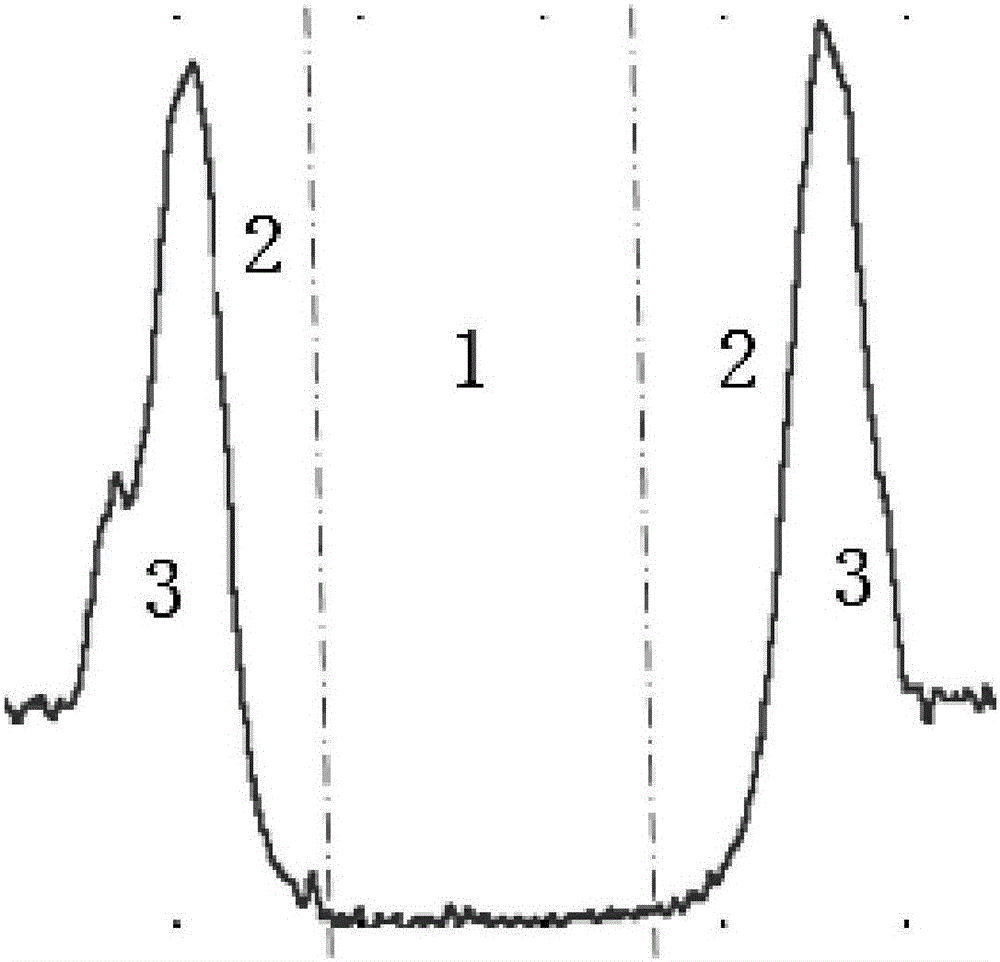
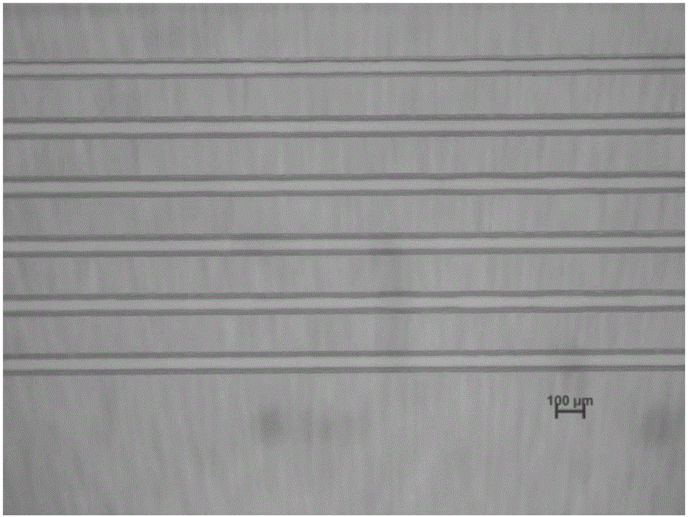
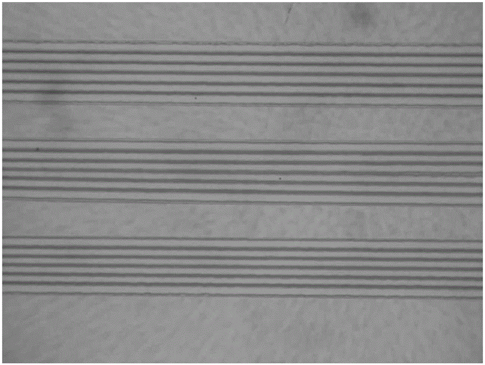
[0030] B. Print a solvent that can dissolve the insulating layer on the surface of the insulating layer. The printed solvent makes the dissolved insulating layer accumulate due to the coffee ring effect to form a pixel wall, and the pixel wall encloses the corresponding pixel limited area. figure 1 It is a schematic diagram of the printed similar structure, the pixel structure is U-shaped, the pixel limited areas 1 and 2 have very little insulating material residue, and 3 is the formed pixel wall.

[0031] Specifically, the inkjet printing method can be used to print the solvent. By adjusting ...

Embodiment 2

[0037] A method for preparing a linear pixel defining layer structure, other features are the same as in Embodiment 1, the difference is that the heat treatment temperature in step D in this embodiment is 190 to 350 degrees Celsius, and the heat treatment time is 6 to 20 minutes. It has been found in practice that the linear pixel defining layer structure prepared by this heat treatment has better performance.

Embodiment 3

[0039] A method for preparing a linear pixel defining layer structure, other features are the same as in Embodiment 1, the difference is that the heat treatment temperature in step D in this embodiment is 200 to 300 degrees Celsius, and the heat treatment time is 6 to 10 minutes. The preparation effect of this process is better.


PUM


Abstract

A preparation method of a linear pixel confining layer structure comprises the following steps of A, depositing a lyotropic insulating layer on the surface of a substrate; B, printing a solvent which can dissolve the insulating layer on the surface of the insulating layer, thereby forming a pixel wall and a pixel confining area; C, performing oxygen ion bombardment processing, and eliminating the insulating layer which residues in the pixel confining area, wherein an integral structure is in a lyophilic state; and D, performing thermal processing so that lyophobicity of the insulating material is partially restored, and the pixel confining area is kept in the lyophilic state. According to the linear pixel confining structure, the pixel confining layer is obtained through printing the solvent on the surface of the insulating layer; the pixel confining area has lyophilicity, thereby facilitating solution expansion; the pixel wall has lyophobicity and can prevent overflowing of the solution; and furthermore because the insulating material can be only dissolved in specific solvents, pixel confining layer corrosion by the solution of a light emitting layer can be prevented. The linear pixel confining layer structure and the preparation method thereof have advantages of simple preparation process and high material utilization rate.

Description

technical field [0001] The invention relates to the technical field of semiconductors, in particular to a linear pixel defining layer structure and a preparation method thereof. Background technique [0002] Organic light emitting diode OLED (Organic light emitting diode) is an organic thin film electroluminescent device, in order to perform color display, OLED needs to be colored. Colorization works best side-by-side. Arranged side by side, there are three sub-pixels of red, green and blue within a pixel range, and each pixel is an independent light-emitting unit. The solution can be precisely printed into the pixel area by inkjet printing to form the light-emitting layer. However, since the droplets formed by printing are of the same size order as the pixel structure, in order to ensure the accuracy of printing and prevent the solution from overflowing to adjacent pixel structures, the current tendency is to use a pixel definition layer. [0003] In the prior art, the p...

Claims


Application Information

Patent Timeline
Patent Type & Authority Applications(China)
IPC IPC(8): H01L27/32H01L51/56
CPCH10K59/122H10K71/00
Inventor 王坚王娟红刘会敏彭俊彪曹镛宋晨郑华
Owner SOUTH CHINA UNIV OF TECH
Why Eureka
Eureka Blog
Learn More