
Oil gas recovery device and method

A recovery device and recovery method technology, applied in chemical instruments and methods, separation methods, gas treatment, etc., can solve the problems of large residual organic matter in adsorbent, low concentration of organic matter in desorbed gas, low condensation recovery efficiency, etc., and achieve good results. Desorption effect, elimination of potential safety hazards, reduction of operating costs and energy consumption

Inactive Publication Date: 2016-11-30
QUANZHOU TIANLONG ENVIRONMENTAL ENG
View PDF8 Cites 21 Cited by
  • Summary
  • Abstract
  • Description
  • Claims
  • Application Information

AI Technical Summary

Problems solved by technology

[0004] Most of the oil and gas produced in petroleum, petrochemical, chemical and other industries have high concentration and low air volume. At present, there are many problems in the commonly used condensation-adsorption-vacuum desorption process: low vacuum desorption efficiency at room temperature, large residual organic matter on the adsorbent, The concentration of organic matter in the desorbed gas is low, the condensation recovery efficiency is low, and too much energy is consumed, resulting in an increase in production costs

Method used


Image

  • Oil gas recovery device and method

Examples


Embodiment Construction

[0021] The present invention will be further described below with reference to the accompanying drawings and specific embodiments, but the present invention is not limited.

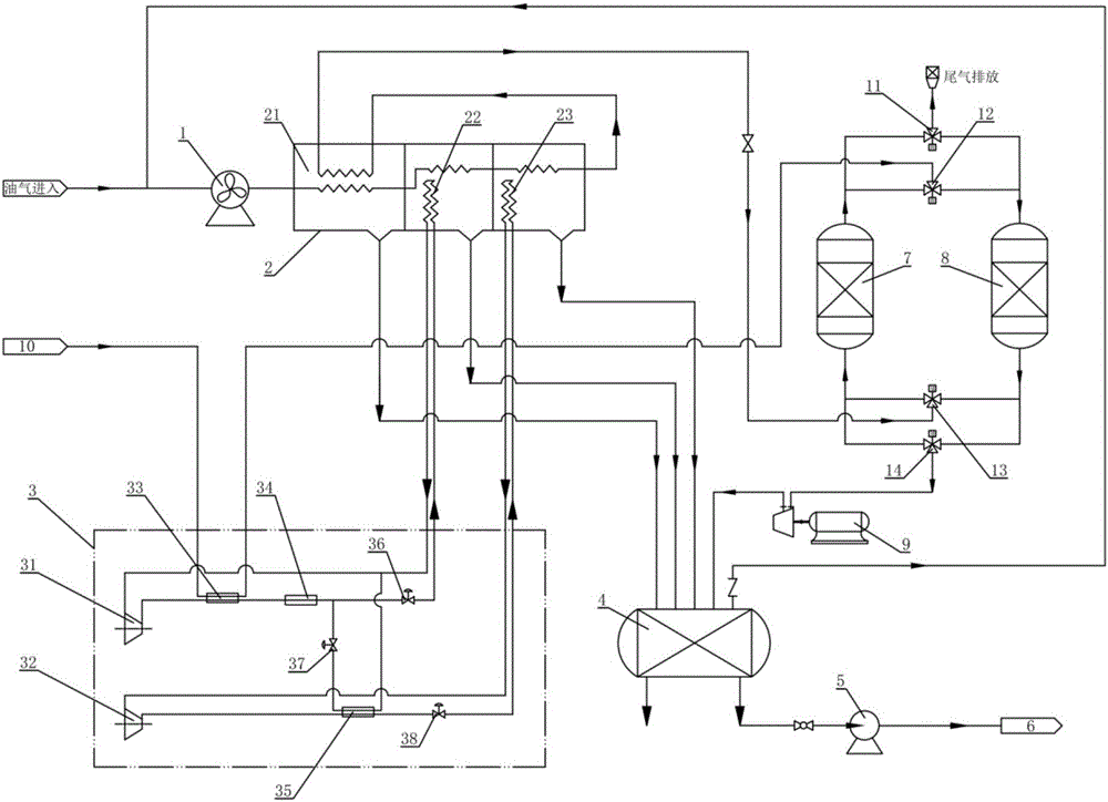
[0022] An oil gas recovery device, comprising an anti-exposure centrifugal fan 1, a cold box 2, a refrigeration unit 3, a liquid storage tank 4, a liquid return pump 5, an oil storage tank 6, a first adsorption tank 7, a second adsorption tank 8, and a vacuum pump 9 , nitrogen generating unit 10, also includes PLC automatic control system; VOCs oil gas is first transported into cold box 2 by anti-exposure centrifugal fan 1, and said cold box 2 includes precooling part 21, primary condensing part 22, secondary condensing part 23 , wherein the secondary condensing part 23 is connected to the precooling part 21, so that the cooling capacity of the precooling part 21 comes from the oil and gas from the secondary condensing part 23, and the primary condensing part 22 and the secondary condensing part 23 are res...


PUM


Abstract

The invention relates to an oil gas recovery device, comprising an anti-exposure centrifugal fan, a cold box, a refrigeration unit, a liquid storage tank, a liquid return pump, an oil storage tank, a first adsorption tank, a second adsorption tank, a vacuum pump, a nitrogen making unit, and Including the PLC automatic control system; the oil and gas are first transported into the cold box by the anti-exposure centrifugal fan, and the liquid oil condensed by the pre-cooling part, the first-level condensing part and the second-level condensing part of the cold box is sent to the liquid storage tank, and then returned to the storage tank. The liquid pump is sent to the oil storage tank for recovery; the oil and gas from the secondary condensing part are sent to the first adsorption tank after the heat is raised by the pre-cooling part, and the first adsorption tank and the second adsorption tank are cycled for adsorption and desorption. When the first adsorption tank or the second adsorption tank enters the desorption stage, the vacuum pump is turned on, and when the vacuum degree of the adsorption tank reaches the set value, the hot nitrogen gas is turned on to desorb the oil and gas with the hot nitrogen gas. By utilizing the advantages of the condensation method and the adsorption method to optimize the combination, the purpose of reducing energy consumption and eliminating potential safety hazards is achieved.

Description

technical field [0001] The invention relates to the field of waste gas treatment, in particular to an oil gas recovery device and method. Background technique [0002] Petroleum, petrochemical, chemical and other industries often emit a large amount of volatile organic compounds such as oil and gas, referred to as VOCs (Volatile Organic Compounds)). VOCs not only seriously deteriorate people's living environment and endanger human health, but also bring serious harm to enterprises and society. Waste of resources, potential safety hazards and economic losses. VOCs mainly include hydrocarbons, alcohols, ethers, aldehydes, phenols, esters, fatty acids, amines, and organic halogen derivatives, among which some organic waste gases have recycling value. With the increasingly stringent emission standards for organic waste gas at home and abroad, the treatment and recovery of VOCs has been paid more and more attention. Their pollution control has always been a key research topic fo...

Claims


Application Information

Patent Timeline
Patent Type & Authority Applications(China)
IPC IPC(8): B01D5/00B01D53/02
CPCB01D5/0036B01D5/0051B01D5/0054B01D5/009B01D53/02B01D2257/708B01D2259/40001B01D2259/4009B01D2259/402
Inventor 傅太平郑孝巨傅灿煌傅金栋黄心明
Owner QUANZHOU TIANLONG ENVIRONMENTAL ENG
Learn More