Combined type water-cooled casting mould integrating directional casting blank solidification and selective area cooling
A technology of directional solidification and water-cooled casting molds, which is applied in the field of metallurgical casting. It can solve the problems that the internal quality of the billet cannot be completely improved, and the casting mold cannot be designed for the round billet. Ratio, the effect of grain uniformity
- Summary
- Abstract
- Description
- Claims
- Application Information
AI Technical Summary
Problems solved by technology
Method used
Image

Examples
Embodiment 1
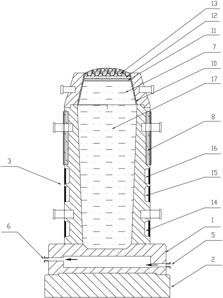
[0046] Place the combined water-cooled casting mold on the lifting platform of the vacuum casting chamber, evacuate to below 10Pa, heat the electrolytic copper to 1200°C with a graphite crucible, add pure silver and zirconium sponge after the metal in the crucible is melted, and continue to heat up the melting temperature to 1300-1350°C, adjust the composition to get NARloy-Z alloy (Cu-3%Ag-0.5%Zr) liquid, cool down and stand still to 1150-1200°C for vacuum casting, slowly lower the lifting table with the rise of the liquid level to ensure immersion The nozzle is always below the liquid level to prevent the alloy liquid from splashing to the inner mold wall. At the end of casting, add the prepared molten glass through the hopper, then add the prepared heating agent, and finally add the covering agent.
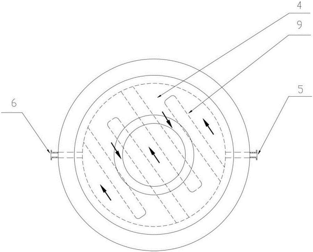
[0047] Open the water inlet 5 to 10 minutes before the upper pouring starts to lower the temperature of the upper chassis and the lower chassis. The alloy liquid is poured int...
Embodiment 2
[0050] Put the combined water-cooled casting mold on the lifting table of the vacuum casting room, evacuate the vacuum to below 10Pa, use the graphite crucible to heat the electrolytic copper to 1200°C, add pure silver and sponge zirconium after the metal in the crucible is melted, and the melting temperature continues to rise to 1300-1350°C, adjust the composition to obtain Cu-Cr-Zr alloy (Cu-0.65%Cr-0.1%Zr) liquid, cool down and stand still to 1220-1250°C for vacuum casting, and slowly lower the lifting table as the liquid level rises , to ensure that the immersion nozzle is always below the liquid level to prevent the alloy liquid from splashing to the inner mold wall. At the end of casting, add the prepared molten glass through the hopper, then add the prepared heating agent, and finally add the covering agent.
[0051] Open the water inlet 5 to 10 minutes before the upper pouring starts to lower the temperature of the upper chassis and the lower chassis. The alloy liquid...
PUM
 Abstract
Description
Claims
Application Information
PatSnap Eureka turns technology decisions into work you can execute. Powered by our Innovation Knowledge Graph, it runs expert workflows across engineering, life sciences, materials and intellectual property. Get your review-ready output in minutes.


