
Self-adaptive stress energy-absorbing tray

A self-adaptive, tray-based technology, applied in mining equipment, earth cube drilling, bolt installation, etc., can solve problems such as difficulty in trench processing, loose surrounding rock, failure of anchoring system, etc., and achieves a simple, safe and reliable structure, which is conducive to recycling , The effect of simple construction technology

Active Publication Date: 2016-12-07
孙燕
View PDF9 Cites 4 Cited by
  • Summary
  • Abstract
  • Description
  • Claims
  • Application Information

AI Technical Summary

Problems solved by technology

[0003] 1. Most of the current pallet designs do not have anti-shock and energy-absorbing capabilities. During the application process of the pallet, due to the impact of surrounding rock and other strong dynamic loads, impact fracture or sudden deformation failure will result in the instantaneous failure of the entire anchoring system.
For example, the Chinese patent application number: 201310686070.2 discloses a kind of anchor tray for underground coal mines, which effectively improves the bending strength of the tray and increases the support area of ​​the tray, but this design only considers the strength of the tray under static load The design and structure are optimized, and it does not have the energy-absorbing and anti-shock damage characteristics of anti-dynamic load impact; the Chinese patent application number 201210210850.5 discloses a double-layer anchor tray. This design considers the protection of the anchor thread from damage during construction, and then Reusing the anchor rod does not have the function of preventing impact failure
[0004] 2. At present, the design of the energy-absorbing tray mainly realizes the tray’s energy-absorbing function on the main body of the tray and the addition of energy-absorbing components. The energy-absorbing design on the main body of the tray changes the original shape of the tray and loses the good performance of the dish-shaped tray. Stress advantages; the structural design of energy-absorbing components is not perfect, the structural parameters are unreasonable, the yielding pressure of energy-absorbing components is unstable, easy to overturn and deform, and the specific energy absorption rate is extremely low
For example, the Chinese patent with the application number CN201010515672 discloses a continuous and gradual pressure anchor tray, which is designed with multiple ring-shaped pressure grooves, and squeezes out of the surrounding rock wall through the disc-shaped tray with grooves. Although this design has a certain pressure-yielding characteristic, the resistance during the pressure-yielding process is unstable and causes crushing and scratching damage to the surrounding rock, causing the surrounding rock to loosen, the bolt to fail, the pallet cannot be reused, and the groove processing is difficult
[0005] 3. Due to the unevenness of the surrounding rock wall of the roadway after construction or during the support process, especially the uneven deformation of the surrounding rock wall under strong impact, the uneven force on the pallet plane causes the pallet body to twist, and the tail of the anchor rod is affected. The force produces a bending moment, which causes the most common shear brittle fracture at the tail of the anchor rod body, resulting in instantaneous failure of the anchoring system
Furthermore, when the anchor rod is subjected to impact loads, the anti-shock and anti-break dual-function integrated design of the pallet has not yet been explored.

Method used


Image

  • Self-adaptive stress energy-absorbing tray
  • Self-adaptive stress energy-absorbing tray
  • Self-adaptive stress energy-absorbing tray

Examples


Embodiment Construction

[0020] The present invention will be described in detail below in conjunction with the accompanying drawings and specific embodiments, where the schematic embodiments and descriptions of the present invention are used to explain the present invention, but not to limit the present invention.

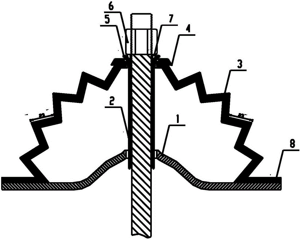
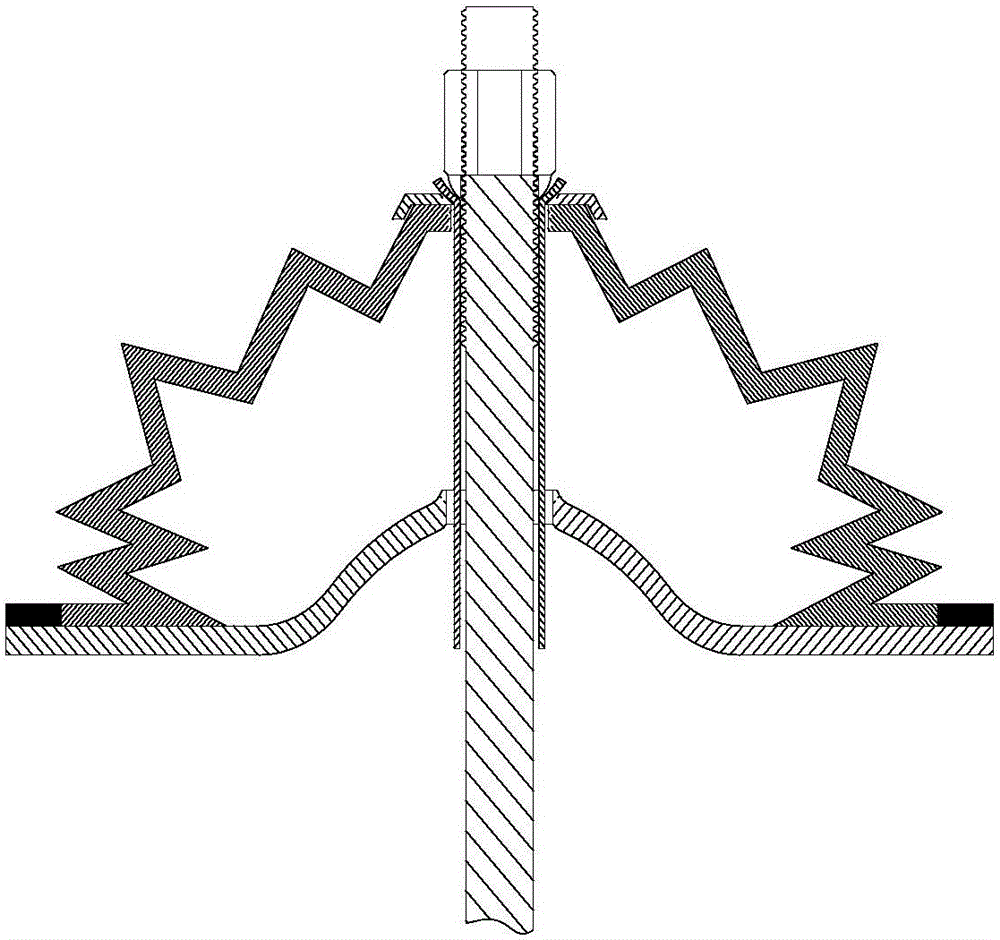
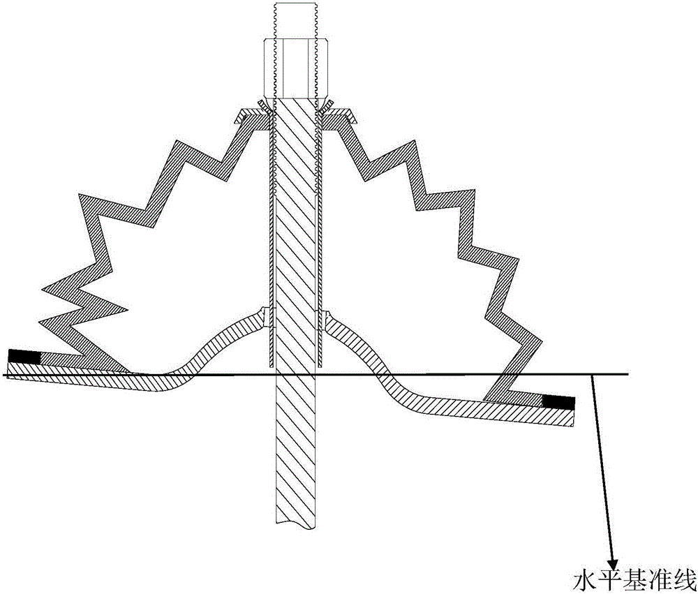
[0021] refer to figure 1 , the purpose of the present invention is to provide an adaptive force-absorbing tray, including a dish-shaped tray 1, the butterfly-shaped tray body 1 gradually forms a convex surface from the horizontal transition on both sides; the top of the dish-shaped tray 1 is a wall from the lower end to the A cone-like energy-absorbing box 3 with plastic hinges that gradually changes at the upper end. The wall thickness of the cone-like energy-absorbing box 3 is 3mm to 5mm, and the length of each wall is 20mm to 28mm. Hinge pattern, the cone-like energy-absorbing box 3 and the center of the disc-shaped tray 1 form an anchor hole, and inside the anchor hole is a bending-re...


PUM

PropertyMeasurementUnit
Wall thicknessaaaaaaaaaa
Lengthaaaaaaaaaa

Abstract

The invention provides a self-adaptive stress energy-absorbing tray making the tray of an anchor pole support system of a mine laneway prevent sudden deformation unloading or cracking under the action of impact load, guarantee efficient stable energy absorption of energy absorbing members, improve the stress of the tray, and prevent impacting torsion and brittle fracture of anchor rod tails. The technical scheme comprises a self-adaptive stress energy-absorbing tray comprising a phialiform tray, wherein a convex surface is formed by gradual horizontal transition of two sides of the phialiform tray; a top of the tray is a type of tapered energy absorbing box with plastic hinge folds that progressively changes from the bottom to the top of walls; the wall thickness of the tapered energy absorbing box is 3mm to 5mm; the length of each wall is 20mm to 28mm; hinge folds are formed among adjacent walls and the fold angle is 60 DEG; an anchor rod hole is formed in the center of the tapered energy absorbing box and the phialiform tray; a bending resistance protection pipe is installed in the anchor rod hole in the periphery direction and the upper end is a hemispherical concave surface of the upper end of the bending resistance protection pipe.

Description

technical field [0001] The invention belongs to the technical field of safety support in underground projects such as mining engineering, water conservancy and hydropower engineering, and tunnel engineering, and in particular relates to an adaptive force-absorbing energy-absorbing tray used for anchor rods (cables). Background technique [0002] In the bolting support of underground roadway, the pallet is an important part in the bolting system. Due to the recognized advantages of dish-shaped pallets, most of the pallets used in coal mines are mainly dish-shaped pallets. Through a large number of analysis of the field application of dish-shaped pallets and related patents and many other documents, it is found that the current dish-shaped pallets have problems in application and design. The following questions: [0003] 1. Most of the current tray designs do not have anti-shock and energy-absorbing capabilities. During the application process, the trays are impacted and frac...

Claims


Application Information

Patent Timeline
IPC IPC(8): E21D21/00
CPCE21D21/0026E21D21/0033E21D21/0093
Inventor 代连朋潘一山王爱文赵鑫
Owner 孙燕
Features
  • Generate Ideas
  • Intellectual Property
  • Life Sciences
  • Materials
  • Tech Scout
  • Unparalleled Data Quality
  • Higher Quality Content
  • 60% Fewer Hallucinations
Learn More