Nitrided high-speed steel roller used for bar cutting rack and manufacturing method of nitrided high-speed steel roller

A technology of nitriding high-speed steel rolls and a manufacturing method, applied in the field of roll manufacturing, can solve problems such as uneven distribution, high labor intensity of workers, and impact on finished products, achieve reduction of carbide-forming elements, shorten roll changing and slot changing time, and stabilize The effect of product negative margin

Active Publication Date: 2016-12-14
邢台轧辊线棒辊有限责任公司
View PDF5 Cites 10 Cited by
  • Summary
  • Abstract
  • Description
  • Claims
  • Application Information

AI Technical Summary

Problems solved by technology

[0004] (1) The life of the rolling groove is low, and the phenomenon of groove collapse occurs from time to time. The number of times of changing rolls and grooves is long and the time is long, which seriously affects the operation rate and output indicators. When the rolling volume reaches about 70t, rolling marks appear on the surface of the steel. To ensure For the size and surface quality of the product, it is necessary to replace the finished groove every about 2 hours, and it takes 10 minutes to replace a new groove. Only the slot change time per day has an impact on the operation rate of more than 9%
[0005] (2) The physical quality of the steel is unstable, and it is difficult to adjust the rolling groove in the later period of use. Due to the low hardness of the rolling groove, the cutting hole and the wedge tip of the pre-slitting hole wear very quickly, resulting in unstable material shape and uneven distribution, which is reflected in the finished product On the steel, there is a large change in the direction and size between each line and a single branch, and the impact on the finished product is more serious at the lat

Method used


Image

  • Nitrided high-speed steel roller used for bar cutting rack and manufacturing method of nitrided high-speed steel roller

Examples


Embodiment 1

[0047] A centrifugal compound nitriding high-speed steel roll suitable for bar splitting racks and its manufacturing method, including molding, melting, nitriding agent treatment, centrifugal casting, casting transition layer and roll neck operation, and pouring core , unpacking, machining and heat treatment steps.

[0048] Step A. Modeling

[0049] The casting box includes a roll body box, a roll neck box and a bottom box. The roll body box is made of metal spray paint, the roll neck box is made of silica sand clay, and the bottom box is connected to the overflow pipe;

[0050] 2. Medium power frequency furnace smelting, molten steel smelting in the working layer of the roll, the melting temperature is 1500-1650°C, the alloy composition of the working layer and the weight percentage of each alloy composition are 1.2-2.2C, 7.0-13.5Cr, 0.2-1.2Ni, 0.5~1.5Mo, 1.0~2.5V, 1.0~2.5W, 1.0~3.0Nb, 0.05~0.1Re, P≤0.04, S≤0.04, Mn≤0.5, 0.6~1.5Si, and the rest is Fe.

[0051] The transitio...

Embodiment 2

[0059] The difference between this embodiment and embodiment 1 is that the alloy composition of the working layer and the weight percentage of each alloy composition are: 1.7C, 10.5Cr, 0.6Ni, 1.0Mo, 1.8V, 1.6W, 2.0Nb, 0.08Re, P ≤0.04, S≤0.04, Mn≤0.5, 1.1Si, the rest is Fe;

[0060] The alloy composition of the transition layer and the weight percentage of each alloy composition are: 2.8C, 0.3Cr, 0.1Re, P≤0.03, S≤0.02, Mn0.5, 1.8Si, and the rest is Fe;

[0061] The alloy composition of the core and the weight percentage of each alloy composition are: 3.2C, 0.4Cr, 0.5Ni, 0.1Re, P≤0.03, S≤0.02, Mn0.7, 1.8Si, and the rest is Fe.

Embodiment 3

[0063] The difference between this embodiment and embodiment 1 is: the alloy composition of the working layer and the weight percentage of each alloy composition are: 2.2C, 13.5Cr, 1.2Ni, 1.4Mo, 2.4V, 2.5W, 3.0Nb, 0.1Re, P ≤0.04, S≤0.04, Mn≤0.5, 1.5Si, the rest is Fe;

[0064] The alloy composition of the transition layer and the weight percentage of each alloy composition are: 3.0C, 0.1~0.5Cr, 0.1Re, P≤0.03, S≤0.02, Mn0.8, 2.0Si, and the rest is Fe;

[0065] The alloy composition of the core and the weight percentage of each alloy composition are: 3.6C, 0.5Cr, 0.8Ni, 0.1Re, P≤0.03, S≤0.02, Mn1.0, 2.0Si, and the rest is Fe.


PUM


Abstract

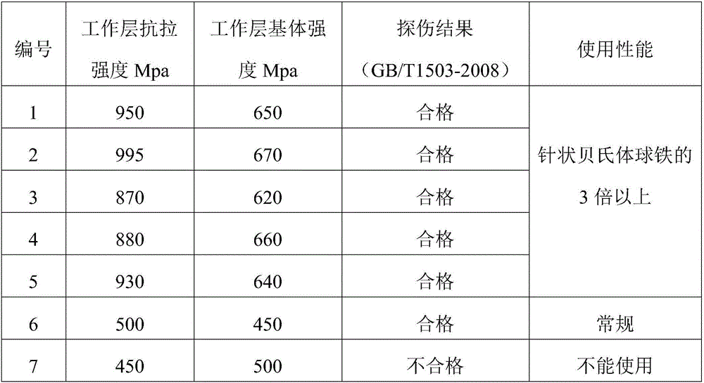
The invention relates to a nitrided high-speed steel roller used for a bar cutting rack and a manufacturing method of the nitrided high-speed steel roller, and belongs to the technical field of roller manufacturing. The nitrided high-speed steel roller comprises a roller neck and a roller body composed of a working layer, a transition layer and a core part. The working layer is composed of, by weight, 1.2-2.2% of carbon, 7.0-13.5% of chromium, 0.2-1.2% of nickel, 0.5-1.5% of molybdenum, 1.0-2.5% of vanadium, 1.0-2.5% of tungsten, 1.0-3.0% of niobium, 0.05-0.1% of rare earth, less than or equal to 0.04% of phosphorus, less than or equal to 0.04% of sulfur, less than or equal to 0.5% of manganese, 0.6-1.5% of silicon and the balance iron. The substrate strength of the working layer is greater than or equal to 600 MPa, and the tensile strength of the working layer is greater than or equal to 800 MPa. The substrate strength of the high-speed steel roller is improved, the grain is refined, the rolling environment requirement of the bar rolling mill cutting rack is met, and the rolling requirement of the cutting rack is met.

Description

technical field [0001] The invention relates to a nitriding high-speed steel roll suitable for a bar cutting frame and a manufacturing method thereof, belonging to the technical field of roll manufacturing. Background technique [0002] In the finishing rolling section of the bar mill, the split rolling technology is usually used. The split rolling technology is to use a billet to roll into two or more finished products of the same size by using the pass and guide. The technology was only applied to profile cutting at first, and the cutting and rolling technology has developed rapidly in some industrially developed countries since the 1970s. [0003] When split rolling is adopted, the traditional acicular bainite ductile iron material is still the majority at present, but the low single-groove rolling capacity of bainite ductile iron rolls and frequent roll changes have become bottlenecks for further increase in production capacity. The main performance In the following res...

Claims


Application Information

Patent Timeline
IPC IPC(8): B21B27/02C22C38/44C22C38/46C22C38/48C22C38/02C22C38/04
CPCB21B27/024C22C38/005C22C38/02C22C38/04C22C38/44C22C38/46C22C38/48
Inventor 李晓刚郭小军贺振轩陈兴富董亮
Owner 邢台轧辊线棒辊有限责任公司
Why Eureka
Try Eureka