
Cylindrical capillary pump assembly of loop heat pipe

A loop heat pipe and capillary pump technology, applied in indirect heat exchangers, lighting and heating equipment, etc., can solve the problems of reducing the service life of the loop heat pipe, increasing the decomposition rate of the working fluid, and reducing the open porosity. The effect of reducing reverse heat leakage, improving mechanical properties, and good chemical stability

Active Publication Date: 2016-12-14
BEIJING RES INST OF SPATIAL MECHANICAL & ELECTRICAL TECH
View PDF8 Cites 20 Cited by
  • Summary
  • Abstract
  • Description
  • Claims
  • Application Information

AI Technical Summary

Problems solved by technology

In the blank, the capillary core can ensure a small pore diameter and a large open porosity. However, when the surface is machined, due to the high ductility of the metal material, turning or wire cutting will cause the surface micropores to close and reduce the open porosity. Rate
On the other hand, as a porous medium, the capillary core has an effective surface area that accounts for the vast majority of the inner wall area of ​​the loop heat pipe, while the metal material has relatively high activity and poor compatibility with the working fluid, resulting in an increase in the decomposition rate of the working fluid and a decrease in Loop Heat Pipe Service Life

Method used


Image

  • Cylindrical capillary pump assembly of loop heat pipe
  • Cylindrical capillary pump assembly of loop heat pipe
  • Cylindrical capillary pump assembly of loop heat pipe

Examples


Embodiment Construction

[0032] Such as figure 2 As shown, it is a schematic structural diagram of a cylindrical loop heat pipe capillary pump assembly of the present invention, which mainly includes a tube shell 1 and a capillary wick 2 . The tube shell 1 is composed of two parts, the evaporator shell 3 and the liquid reservoir shell 4 . One section of the capillary 2 is located inside the evaporator housing 3, and the other section extends into the interior of the liquid reservoir housing 4, so that two independent cavities of the vapor chamber and the liquid storage chamber are formed inside the capillary pump assembly.

[0033] The evaporator shell 3 includes a first main shell 11 and a second main shell 12. The inner wall of the main shell 11 is provided with axial micro channels, and the inner wall of the second main shell 12 is designed to be smooth. The outer wall of the capillary core 2 located at the inner section of the evaporator housing 3 closely cooperates with the inner wall of the fi...


PUM

PropertyMeasurementUnit
Effective apertureaaaaaaaaaa
Bending strengthaaaaaaaaaa
Thermal conductivityaaaaaaaaaa

Abstract

A cylindrical capillary pump assembly of a loop heat pipe comprises an evaporator shell (3), a liquid accumulator shell (4) and a capillary core (2). The liquid accumulator shell (3) is connected with the evaporator shell (4). One section of the capillary core (2) is located inside the evaporator shell (3). The other section of the capillary core (2) stretches into the liquid accumulator shell (4). The capillary core (2) is formed by sintering porous silicon nitride, and good porosity, good chemical stability, a low heat conductivity coefficient and a good machining property are achieved. A local part of the junction of the liquid accumulator shell (3) and the evaporator shell (4) is designed to be of an S-shaped structure; and the heat conduction path is long, the heat conductivity coefficient is relatively low, and the probability of leakage of heat from an evaporator to a liquid accumulator can be lowered. According to the cylindrical capillary pump assembly of the loop heat pipe, it can be guaranteed that the loop heat pipe has good starting performance, a good heat transfer property and a long service life, and can well adapt to a spatial microgravity environment and a mechanical environment on a spacecraft launching section at the same time.

Description

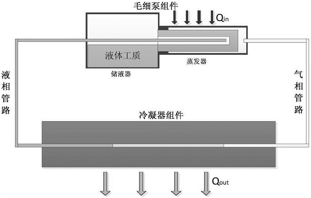
technical field [0001] The invention belongs to the field of heat control, and relates to a loop heat pipe, in particular to a capillary pump component used in the loop heat pipe. Background technique [0002] Loop heat pipe (LHP) is a two-phase fluid circuit system that uses capillary force to drive the circulation of working fluid to complete heat exchange. It quickly transfers the heat from the heat source to the heat sink through a flexible pipeline. The required flexible heat transfer link has the advantages of small heat transfer temperature difference, large heat transfer power, long heat transfer distance, high temperature control accuracy and flexible installation. Based on this, the loop heat pipe has become an advanced precision thermal control product with broad development prospects in the precision thermal control system. Its working principle is as follows: figure 1 shown. [0003] The start-up characteristics, heat transfer capacity and life reliability of ...

Claims


Application Information

Patent Timeline
IPC IPC(8): F28D15/04
CPCF28D15/043F28D15/046
Inventor 罗世魁李春林杨涛赵石磊高腾潘浩张焕冬颜吟雪
Owner BEIJING RES INST OF SPATIAL MECHANICAL & ELECTRICAL TECH
Learn More