
Solid barrier needle point contact type scanning tunnel microscope

A scanning tunneling and microscope technology, applied in the field of scanning probe microscopy, can solve the problems of limited selection of needle tips, unfavorable STM, false atoms, etc., to avoid troublesome and tedious processes, improve STM resolution, and improve the effect of the probability of success.

Active Publication Date: 2016-12-14
HENAN NORMAL UNIV
View PDF2 Cites 5 Cited by
  • Summary
  • Abstract
  • Description
  • Claims
  • Application Information

AI Technical Summary

Problems solved by technology

However, STM only has two modes of contour and constant current in the non-contact mode. The single mode is not conducive to the popularization, application and development of STM.
[0005]3. At present, the material selection of STM needle tip is extremely limited, basically all of them are tungsten or platinum-iridium alloy
It also poses a great challenge in the selection of
[0006]4. The current STM is too strict on shock absorption, which causes all STM teams to attach great importance to shock absorption and spend a lot of time, money and energy to build shock absorbers
[0009] In order to overcome the above-mentioned false atoms in STM, the inability to measure surface topography synchronously, single working mode, the probe must be inert or must rely on high vacuum equipment, shock resistance requirements With the support of the National Natural Science Foundation of China with the project approval number: 11304082 "Improvement and Application of Ultra-fast Scanning Tunneling Microscope", this patent proposes a solid-state barrier needle-tip contact mode scanning tunneling microscope

Method used


Image

  • Solid barrier needle point contact type scanning tunnel microscope
  • Solid barrier needle point contact type scanning tunnel microscope
  • Solid barrier needle point contact type scanning tunnel microscope

Examples


Embodiment 1

[0045] Contour Elastic Contact Scanning Tunneling Microscope

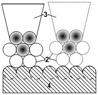
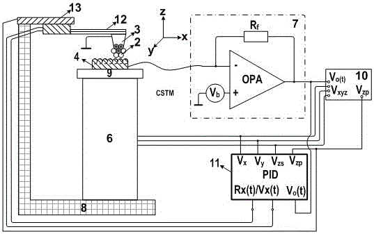
[0046] The contour elastic contact scanning tunneling microscope is one of the various implementations of the elastic contact scanning tunneling microscope. Its characteristic feature is that the distance between the probe station 13 and the sample stage 9 remains constant, and the barrier needle tip formed by the conductive tip 3 and the solid dielectric film 2 fluctuates with the fluctuation of the surface of the conductive sample, which can also be referred to as a contour contact mode, which is similar to The probe-sample stage spacing remains unchanged for non-contact mode STM similarly.

[0047] The obtained varying output current still reflects the electronic density of states distribution on the surface of the conducting sample. The contour contact mode STM is similar to the non-contact mode STM, and has complementary characteristics and advantages in the mode.

[0048] In the specific operation, first us...

Embodiment 2

[0056] Constant force elastic contact scanning tunneling microscope

[0057] In Example 1, the CSTM in the constant-height contact mode is not suitable for samples with large surface fluctuations, and may damage the probe or the sample. For this reason, the distance between the probe and the sample needs to fluctuate with the fluctuation of the sample surface. The adopted solution is constant force mode CSTM with PID feedback control.

[0058] At this time, the elastic cantilever needle body 12 including piezoresistive material or piezoelectric material can be selected to sense the force between the solid barrier needle tip and the conductive sample 4 . Resistance of piezoresistive or piezoelectric needles R x (t) or voltage V x (t), connected to the detection circuit through two electrodes, such as a bridge circuit, the output of the bridge is connected to the PID controller 11 that adjusts the distance between the probe station 13 or the sample stage 9, and makes the ou...


PUM


Abstract

The invention discloses a solid barrier needle point contact type scanning tunnel microscope. A conductive probe is formed by a conductive probe body and a conductive needle point arranged on the free end of the conductive probe body, wherein at least one layer of solid dielectric film is covered on the conductive needle point to form a solid barrier needle point. During an imaging process, the height of a sample bench or / and a probe bench is adjusted to allow the solid barrier needle point to scan in a way of contacting a sample, and the obtained tunneling current passing through the solid barrier needle point is input to a scanning tunnel microscope testing system and / or the current amplification circuit of a conductive atomic force microscope testing system. Obtained output and corresponding coordinate information of the tunneling current are input to the scanning tunnel microscope testing system and / or a data processing and imaging module of the conductive atomic force microscope testing system, and the electronic state density distribution information of a sample surface is obtained. The novel working mode of the scanning tunnel microscope is created, the anti-vibration capability and success rate are high, the cost is low and the resolution is high.

Description

technical field [0001] The invention belongs to the technical field of scanning probe microscopes with new principles, and in particular relates to a scanning tunneling microscope in a solid-state potential barrier needle tip contact mode. Background technique [0002] Scanning Tunneling Microscope (STM), with its highest spatial resolution today, is the only instrument capable of characterizing the distribution of electronic density of states on the surface of a sample, and has played an irreplaceable and crucial role in the fields of surface technology and nanotechnology, but There are also several huge problems: [0003] 1. Due to the principle of superposition of electronic density of states, pseudo atoms will appear in STM. The ripple in the quantum fence is one of the illusions, but how to verify it is an illusion? Before and after the establishment of the quantum fence, in addition to the redistribution of the electronic density of states, is there any redistributio...

Claims


Application Information

Patent Timeline
Patent Type & Authority Applications(China)
IPC IPC(8): G01Q60/10G01Q60/16
CPCG01Q60/10G01Q60/16
Inventor 李全锋
Owner HENAN NORMAL UNIV
Learn More