Photon orbit angular momentum measurement system and method based on wave-front conversion method

An orbital angular momentum, measurement system technology, applied in the field of single-photon detection, can solve the problems of large error, detection error, exponential increase in cascade difficulty, etc., to achieve a large degree of freedom of operation, enhanced imaging effect, and strong repeatability Effect

Active Publication Date: 2017-01-04
黑龙江省工业技术研究院
View PDF4 Cites 27 Cited by
  • Summary
  • Abstract
  • Description
  • Claims
  • Application Information

AI Technical Summary

Problems solved by technology

The traditional intensity interference method is not suitable for the measurement of orbital angular momentum of weak signals at the photon level. The traditional interferometer cascade detection method, for the case of many types of orb

Method used


Image

  • Photon orbit angular momentum measurement system and method based on wave-front conversion method
  • Photon orbit angular momentum measurement system and method based on wave-front conversion method
  • Photon orbit angular momentum measurement system and method based on wave-front conversion method

Examples


specific Embodiment approach 1

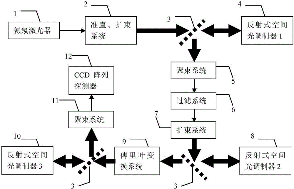
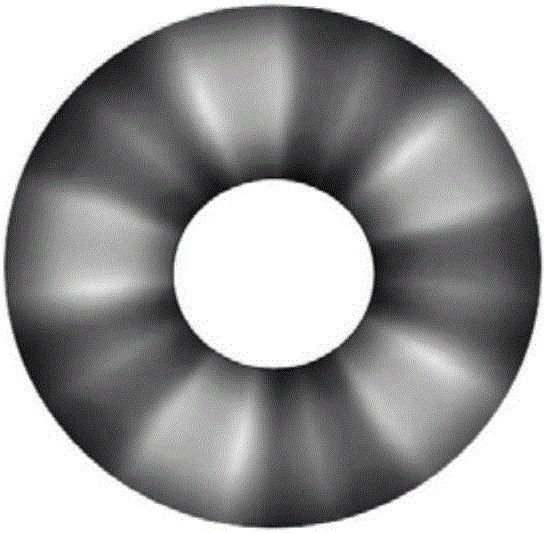
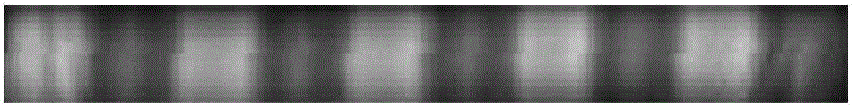
[0030] Specific implementation mode one: as Figures 1 to 5 As shown, the photon orbital angular momentum measurement system based on the wavefront conversion method described in this embodiment includes a helium-neon laser 1, a collimated beam expander system 2, three beam splitters 3, and a first reflective spatial light modulator 4. The second reflective spatial light modulator 8, the third reflective spatial light modulator 10, the first beamforming system 5, the second beamforming system 11, the filtering system 6, the beam expanding system 7, and the Fourier transform system 9 and a CCD array detector 12;

[0031] The helium-neon laser 1 is used to generate a Gaussian laser beam, and the collimated beam expander system 2 is used to expand the laser signal; the first beam splitter 3 transmits part of the expanded laser signal and continues to transmit it to the first reflection type Spatial light modulator 4; the first reflective spatial light modulator 4 loads a spiral ...

specific Embodiment approach 2

[0034] Specific implementation mode two: as figure 1 As shown, in this embodiment, the orbital angular momentum beam is generated using a reflective spatial light modulator loaded with a spiral phase pattern, and the reflective spatial light modulator is a 1920x1152 high-resolution liquid crystal spatial light modulator. Other compositions and connections are the same as in the first embodiment.

specific Embodiment approach 3

[0035] Specific implementation mode three: as figure 1 As shown, in this embodiment, the receiving end uses a CCD array detector to perform one-time focused imaging on the modulated light beam. Other compositions and connections are the same as those in Embodiment 1 or Embodiment 2.


PUM

PropertyMeasurementUnit
Wavelengthaaaaaaaaaa
Bandwidthaaaaaaaaaa

Abstract

The invention discloses a photon orbit angular momentum measurement system and a method based on a wave-front conversion method, which belong to the technical field of single photon detection in a quantum technology, solve the problem that the existing photon-magnitude orbit angular momentum detection needs multiple interferometers to be cascaded, and can simply, conveniently and accurately measure the photon-magnitude orbit angular momentum. Transmitted laser signals are modulated through multiple times of a spatial light modulator and a Fourier transformation system; the modulated signal pulses with the orbit angular momentum are gathered to a CCD detection array; and the quantum number in the orbit angular momentum in the signals can be distinguished through a pattern position on the detector, different azimuth angles are corresponding to different lateral coordinates, and the quantum number 1 in the orbit angular momentum can be determined as coordinates are measured. The system and the method of the invention are applied to measurement on the quantum number in the single-photon magnitude orbit angular momentum.

Description

technical field [0001] The invention relates to a photon orbital angular momentum measurement system and method, and relates to the technical field of single photon detection in quantum technology. Background technique [0002] Photon orbital angular momentum can load infinite multi-dimensional information, and it is a good carrier of information in the fields of communication and detection. Sometimes the echo signal is very weak, and there is currently a lack of detection methods for photon-level orbital angular momentum. The traditional intensity interference method is not suitable for the measurement of orbital angular momentum of weak signals at the photon level. The traditional interferometer cascade detection method, for the case of many types of orbital angular momentum, the difficulty of cascading increases exponentially, and a large number of analysis Beamers will cause detection errors due to instrument imperfections and transmission losses, and the more types, the...

Claims


Application Information

Patent Timeline
IPC IPC(8): G01J3/28
CPCG01J3/2803
Inventor 张子静赵远张建东苏建忠王峰
Owner 黑龙江省工业技术研究院
Why Eureka
Try Eureka