

Low temperature X ray induced thermoluminescence spectrum measuring device
A measurement device, thermoluminescence technology, applied in the direction of measurement devices, material analysis using wave/particle radiation, instruments, etc., can solve the problems of affecting the content of analysis information, poor spectral repeatability, detection, etc., to achieve good spectral repeatability, The effect of enriching data information and reducing the overall volume
Inactive Publication Date: 2017-01-04
SHANGHAI INST OF CERAMIC CHEM & TECH CHINESE ACAD OF SCI +1
View PDF3 Cites 5 Cited by
- Summary
- Abstract
- Description
- Claims
- Application Information
AI Technical Summary
Problems solved by technology
[0005] At present, there is no low-temperature X-Ray induced thermoluminescence spectroscopy measurement device in China. Existing thermoluminescence instruments can only measure thermoluminescence signals above room temperature. ray irradiation and spectral reception are very difficult
However, as mentioned above, the trap depth inside the material is directly related to the temperature. For example, the positional defects of scintillation materials generally appear between 100K-200K, so the existing thermoluminescence cannot detect these shallow energy level defects. Measurement range limits application of this technique for materials research and inspection
[0007] 1. The monochromator needs to be equipped with a driving part that drives the grating to rotate, so its volume and power consumption are large, resulting in the volume and power consumption of the entire device are too large, and the time period for obtaining the fluorescence spectrum is long, and the fluorescence spectrum cannot be realized. Real-time collection of spectra, so some transient characteristics of fluorescent signals cannot be analyzed, and spectral repeatability is poor;
[0008] 2. Only the X-Ray induced fluorescence spectrum was measured, and the X-Ray induced thermoluminescence spectrum in the longer wavelength range could not be measured, which affected the information content of the analysis;
[0009] Existing thermoluminescence instruments only have a thermoluminescence test system above room temperature, the main reason is that the existing technology does not integrate a sample chamber that can be cooled by liquid nitrogen or liquid helium
Method used
View moreImage
Smart ImageViewing Examples

Examples
Embodiment 1
[0072] Figure 6 It is the schematic diagram of the X-Ray induced low-temperature thermoluminescence test system, in which the maximum voltage of the X-Ray light source is 90Kv, and the current is 2-2.5mA; the temperature range of the sample chamber is 77K (liquid nitrogen temperature)-500K, and the heating rate is <6K / min (adjustable); the detection sensitivity of the spectrometer is 26 photons (@250nm). The main indicators of the final test system are shown in the table below:
[0073]
Login to View More PUM
 Abstract
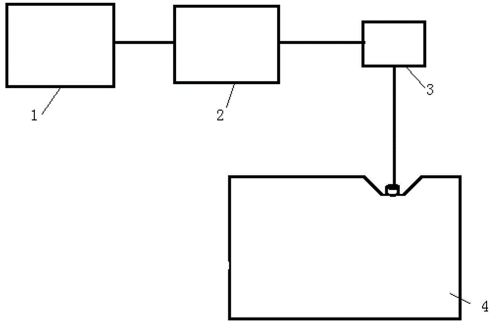
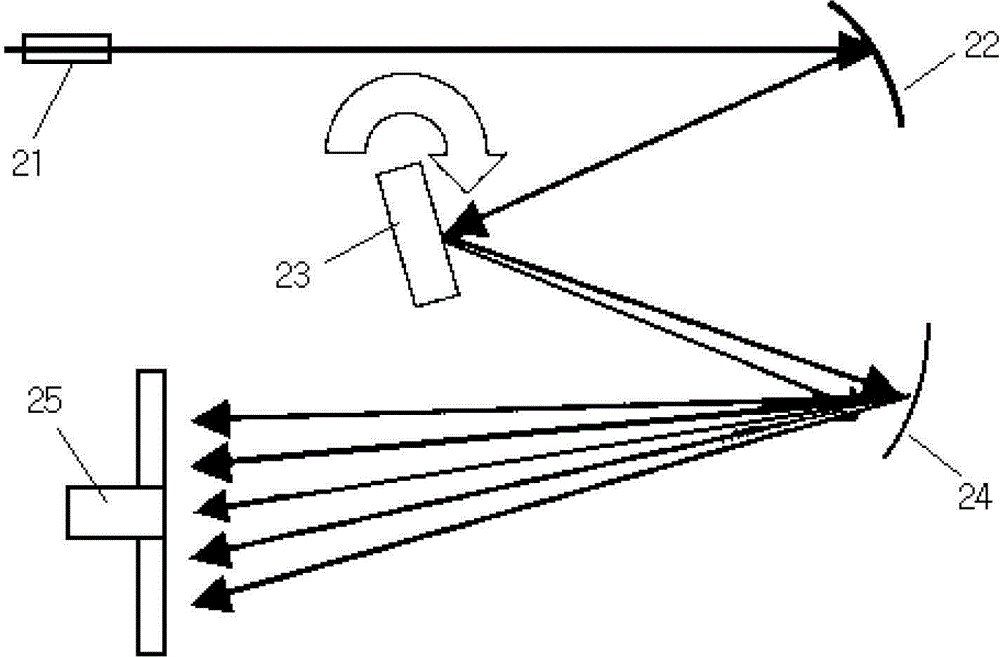
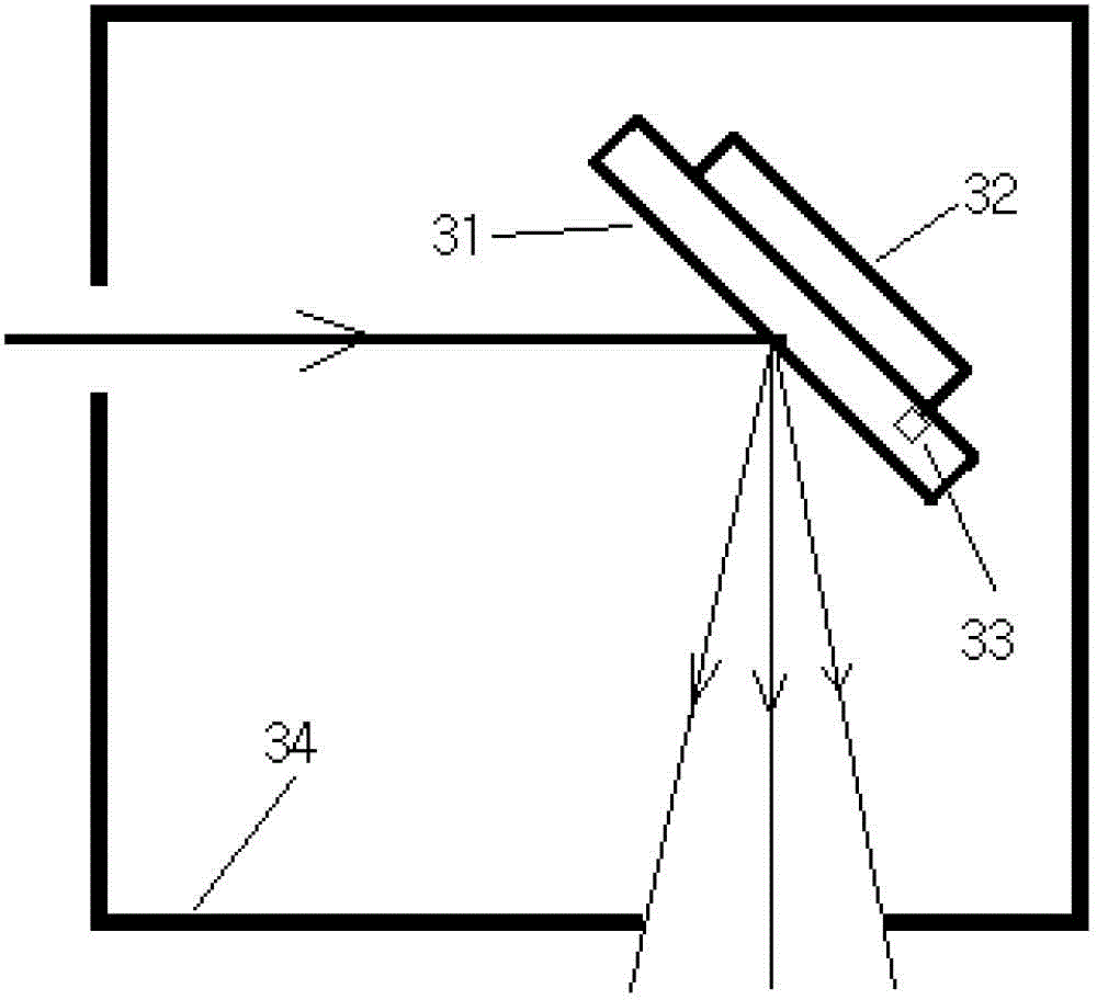
The invention relates to a low temperature X ray induced thermoluminescence spectrum measuring device. The low temperature X ray induced thermoluminescence spectrum measuring device comprises an X ray source, a temperature control unit, and a sample stage, a light collecting system, and a grating spectrometer which are arranged in the temperature control unit; the temperature control unit comprises a thermal-insulation housing, and a temperature sensor and a heating refrigerator which are arranged in the thermal-insulation housing. According to the low temperature X ray induced thermoluminescence spectrum measuring device, the grating spectrometer is introduced, a reflective blazed flat-field grating is adopted by the grating spectrometer to realize dispersion of optical signals, an imaging sensor is used for capturing full spectrum wavelength signal light spectrum at one time, spectrum acquisition time period is extremely short (as short as 1ms), spectrum real-time acquisition is realized, spectrum repeatability is high, utilization of some instantaneous characteristics of optical signals is realized, device whole size is reduced, and device whole power consumption is reduced.
Description
technical field [0001] The invention relates to the fields of X-Ray rays, high and low temperature control and spectrum detection, in particular to an X-Ray induced thermoluminescence spectrum detection device. Background technique [0002] Electron-hole pairs are generated when a material is irradiated by high-energy particles (such as X-rays, gamma rays, etc.). In the process of material preparation, various defects (electron traps, hole traps, anti-site defects, etc.) will inevitably exist due to the limitation of the preparation process. After being irradiated by high-energy rays, the electrons or holes in the excited state will be absorbed by the material The trapping of defects temporarily stores radiant energy in the trap. But these energy levels are unstable, and when heated, the energy in the trap is released in the form of light, a phenomenon known as thermoluminescence. Thermoluminescence is of great significance to materials research and understanding of the lu...
Claims
Login to View More Application Information
Patent Timeline
 Patent Type & Authority Applications(China)
IPC IPC(8): G01N23/223
Inventor 寇华敏于永爱胡辰王伟李伟石云李超宇潘裕柏冯锡淇郭景坤
Owner SHANGHAI INST OF CERAMIC CHEM & TECH CHINESE ACAD OF SCI