Ultrasonic vibration-assisted screw induction hardening device and technique

An ultrasonic vibration and induction quenching technology, applied in the field of quenching devices, can solve the problems of uneven quenching of the lead screw, uneven hardness of the lead screw, inability to obtain martensite structure, etc., achieve uniform austenitization, improve surface performance, The effect of avoiding soft point defects

Active Publication Date: 2017-01-11
SHANDONG UNIV OF SCI & TECH
View PDF5 Cites 9 Cited by
  • Summary
  • Abstract
  • Description
  • Claims
  • Application Information

AI Technical Summary

Problems solved by technology

[0005] The existing workpiece, especially the quenching process of the lead screw, cannot obtain a relatively uniform martensitic structure due to the existence of grooves o

Method used


Image

  • Ultrasonic vibration-assisted screw induction hardening device and technique

Examples


Embodiment Construction

[0037] The technical solutions in the embodiments of the present invention will be clearly and completely described below in conjunction with the drawings in the embodiments of the present invention.

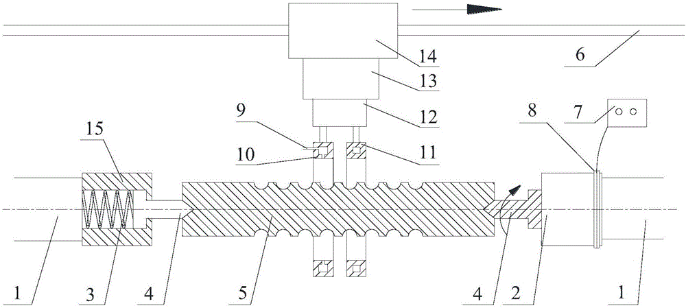
[0038] In this embodiment, the 5010-type ball screw is taken as an example. An ultrasonic vibration-assisted induction hardening device includes an ultrasonic vibration device and an induction hardening device. Specifically, it includes two rotating shafts, two thimbles 4, one thimble 4 connected to an elastic Element 3, the elastic element 3 is fixed in the housing 15 on one side of the second rotating shaft, the elastic element is in a natural state or compressed state in the housing, a through hole is provided on one side of the housing, and the head of the thimble 4 is arranged in the housing Inside, one end of the thimble is set outside the shell through a through hole to clamp the screw from both sides of the screw. The tail of the thimble 4 is pointed to support the screw....


PUM


Abstract

The invention discloses an ultrasonic vibration-assisted screw induction hardening device and a technique. The device comprises a rotating shaft, a first ultrasonic vibrator and two screw fixers, wherein the rotating shaft is used for driving a screw to rotate and is fixed on a machine tool; one end of the first ultrasonic vibrator is fixedly arranged on the end part of the first rotating shaft; one end of a first screw fixer is fixed together with the first ultrasonic vibrator while the other end of the first screw fixer is used for clamping one end of the screw; one end of a second screw fixer is fixed in a shell and is in contact with an elastic component in the shell; the second screw fixer can compress the elastic component; the continuous ultrasonic vibration assistance is performed in the heating and cooling processes of the screw, so that the screw heating is more uniform. Therefore, the soft point defect of the screw surface caused by the insufficient cooling can be prevented, more uniform hardness distribution can be acquired, the performance of the screw surface can be improved and the cooling water dosage can be saved.

Description

technical field [0001] The invention relates to a quenching device, in particular to an ultrasonic vibration-assisted induction quenching device and process for a lead screw. Background technique [0002] Ball screw is a key part used in many industrial equipment and CNC machine tools. However, the poor reliability and low precision of domestic ball screw have become a stumbling block in the development of precision and high-end equipment in my country. The ball screw works under alternating load and bears rolling friction, so the groove should have high contact fatigue strength, wear resistance and dimensional stability. In actual production, it is found that after the screw is ground, axial or mesh cracks often appear on the surface of the screw. The appearance of grinding cracks is not only related to the material itself and the grinding process, but also related to the heat treatment process. When the lead screw is used in production and use, the cracks may be due to e...

Claims


Application Information

Patent Timeline
IPC IPC(8): C21D1/10C21D1/667C21D9/00C21D1/04
CPCC21D1/04C21D1/10C21D1/667C21D9/0062C21D9/0068Y02P10/25
Inventor 李辉平刘海娟贺连芳张春芝
Owner SHANDONG UNIV OF SCI & TECH
Why Eureka
Try Eureka