Polarization modulation Raman probe using spatial output Laser, and spectral detection method

A polarization modulation and laser technology, applied in the field of laser excitation spectrum detection, can solve the problems of high cost, unsuitable for high-power lasers, etc., and achieve the effects of low passive cost, large sampling range, and reduced power density.

Active Publication Date: 2017-01-11
BEIJING HTNOVA DETECTION TECH CO LTD
View PDF10 Cites 2 Cited by
  • Summary
  • Abstract
  • Description
  • Claims
  • Application Information

AI Technical Summary

Problems solved by technology

[0009] In order to solve the problem in the prior art that the energy of the excitation signal coupled into the spectrometer is limited by the slit and the cost of the depolarization processing method is high, and it is not suitable for high-power lasers in the prior art, the present invention provides a laser that uses a spatial output Polarization-modulated Raman probe and spectral detection method

Method used


Image

  • Polarization modulation Raman probe using spatial output Laser, and spectral detection method
  • Polarization modulation Raman probe using spatial output Laser, and spectral detection method
  • Polarization modulation Raman probe using spatial output Laser, and spectral detection method

Examples


Embodiment 1

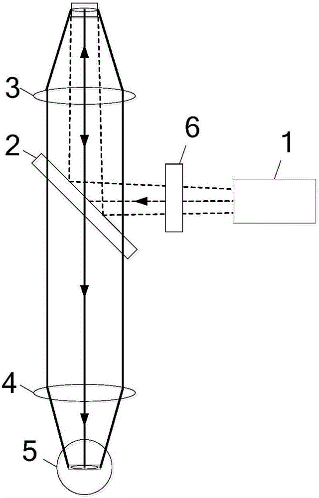
[0051] figure 2 It is the structural diagram of the depolarized polarized Raman probe in the first embodiment. The depolarized polarization Raman probe includes: a spatial output laser 1 , an optical path conversion device 2 , an aggregation collection device 3 , a coupling filter device 4 , a spectrometer 5 , and a wave plate 6 .

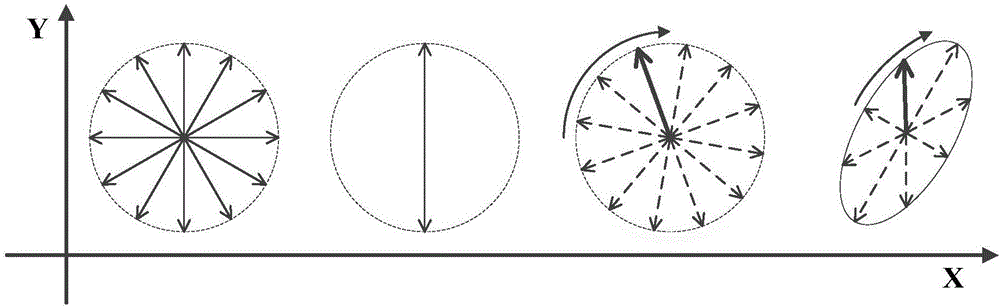
[0052] The spatial output laser 1 is used to output laser beams whose divergence angles in the long axis direction and the short axis direction are inconsistent; the laser beam is linearly polarized light; the laser 1 can be a spatial stripe spot output laser.

[0053] The optical path conversion device 2 is arranged on the output optical path of the laser beam output by the spatial output laser 1, and is used to reflect the laser beam;

[0054] The collecting and collecting device 3 is arranged on one side of the optical path converting device 2 in a manner perpendicular to the laser beam reflected by the optical path converting device 2, and is...

Embodiment 2

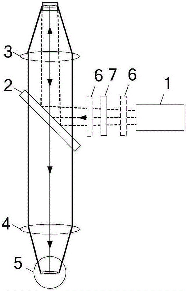
[0059] image 3 is the structure diagram of the depolarized polarized Raman probe in the second embodiment. The difference between Embodiment 2 and Embodiment 1 is that the depolarized polarization Raman probe also includes a purification filter arranged between the spatial output laser 1 and the optical path conversion device 2 in a manner perpendicular to the laser beam output by the spatial output laser 1. The light sheet 7 and the purification filter 7 can purify the laser wavelength components and filter out stray light interference. The wave plate 6 is arranged between the spatial output laser 1 and the purification filter 7 in a manner perpendicular to the laser beam output by the spatial output laser 1, or the wave plate 6 is arranged in a manner perpendicular to the laser beam output by the spatial output laser 1 Between the purification filter 7 and the optical path conversion device 2 .

Embodiment 3

[0061] Figure 4 is the structural diagram of the depolarized polarized Raman probe in the third embodiment. The difference between embodiment three and embodiment two is that the depolarized polarization Raman probe also includes a notch filter 8 arranged between the optical path conversion device 2 and the coupling filter device 4, and the notch filter 8 It is used to block the collected Rayleigh scattered light, and to eliminate stray light signals in the interference band.

[0062] Another configuration of the depolarized polarized Raman probe is described below. In Embodiments 1, 2, and 3, the wave plate 6 is arranged on the optical path between the spatial output laser 1 and the optical path conversion device 2, while in the following embodiments, the wave plate 6 is arranged at the focus of the optical path conversion device 2 and the collection device 3 on the light path between.


PUM


Abstract

The invention discloses a polarization modulation Raman probe using a spatial output Laser, and a spectral detection method. The probe comprises a spatial output laser, an optical path conversion device, an aggregation acquisition device, a coupling filter device, a spectrometer and a wave plate. The wave plate is disposed in a light path between the spatial output laser and the optical path conversion device, or disposed in a light path between the optical path conversion device and the aggregation acquisition device. The probe utilizes a design of a laser with a mode of non-axisymmetrical spatial strip light spot output parallel to the slit direction, so that the divergence angles of the long axis direction and the short axis direction of the laser match the slit, and gathered laser energy having the same energy is distributed in a strip shape instead of circular shape. The laser beam is subject to a passive processing, so that coupling efficiency of the spectrometer can be improved, the collecting efficiency of the system can be improved, and the cost of the device and instrument is reduced.

Description

technical field [0001] The invention relates to the technical field of laser excitation spectrum detection, in particular to a polarization modulation Raman probe and a spectrum detection method using a spatial output laser. Background technique [0002] Raman spectrum is a kind of scattering spectrum. Raman spectroscopy is based on the Raman scattering effect discovered by Indian scientist C.V. Raman (Raman). It analyzes the scattering spectrum different from the frequency of the incident light to obtain molecular vibration and rotation information, and is applied to the study of molecular structure. a method of analysis. Raman spectroscopy has been rapidly developed and widely used in the field of non-invasive detection due to its sensitivity, rapidity and convenient operation. [0003] Spectrum analyzers based on gratings / prisms are currently the most widely used spectral detection equipment, and their optical structures mainly include: slits, collimating optical system...

Claims


Application Information

Patent Timeline
Patent Type & Authority Applications(China)
IPC IPC(8): G01J3/44G01J3/02
CPCG01J3/0208G01J3/0224G01J3/44
Inventor 熊胜军夏征
Owner BEIJING HTNOVA DETECTION TECH CO LTD
Why Eureka
Try Eureka