
Micro-fluidic chip for cell capture and fluorescent staining

A microfluidic chip and fluorescent dyeing technology, which is applied in the field of fluorescent dyed microfluidic chip and cell capture, can solve the problems of easy blockage of the flow channel, cumbersome operation steps, and large manual operation errors, so as to shorten the reaction time and increase the The effect of capturing efficiency and increasing work efficiency

Inactive Publication Date: 2017-01-25
SHANGHAI YH HEALTH BIOLOGY MEDICINE TECH CO LTD
View PDF8 Cites 12 Cited by
  • Summary
  • Abstract
  • Description
  • Claims
  • Application Information

AI Technical Summary

Problems solved by technology

However, solid staining on glass slides generally requires manipulation on the surface of a poly-lysine-coated carrier, which requires certain experimental skills of the operator
And because the slides need to be cleaned repeatedly between each of the above operations, it is easy to cause the loss of cells on the slides. In addition, the cells on the slides are exposed to the air during the processing, which is also easy to cause pollution.
However, liquid staining needs to be detected by flow cytometry, which is costly and requires at least 10 centrifugation operations, which not only consumes a long time and manpower, but also easily causes cell disintegration during the process of discarding the supernatant. loss
[0007] To sum up, the existing cell capture and staining methods have the following problems: after the sample is captured by cells, manual operation is required for cell staining, which is not only cumbersome, but also requires operators to have strong experimental skills. The error is large, which affects the accuracy of the measurement results
And for microfluidic chips to capture target cells, due to the large size of target cells, the flow channel is easy to block, causing target cells to rupture, or cells to escape, resulting in low capture efficiency

Method used


Image

  • Micro-fluidic chip for cell capture and fluorescent staining
  • Micro-fluidic chip for cell capture and fluorescent staining
  • Micro-fluidic chip for cell capture and fluorescent staining

Examples


Embodiment Construction

[0038] Taking the capture and fluorescent staining of CTCs as an example in conjunction with the accompanying drawings, the present invention will be further described through specific examples: For experimental methods that do not indicate specific conditions in the following examples, select according to conventional methods and conditions, or according to the product manual.

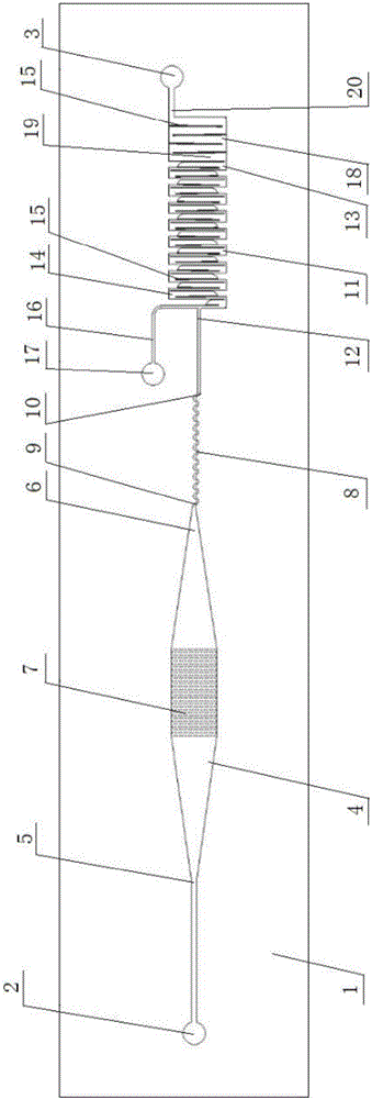
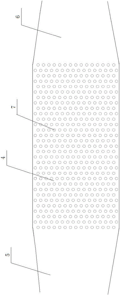
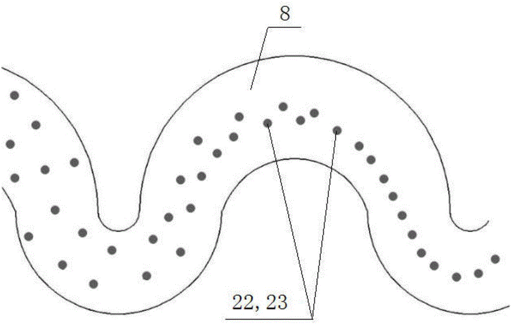
[0039] like figure 1 As shown, the microfluidic chip of the present invention includes a substrate 1 and an upper cover (not shown in the figure). The substrate 1 sequentially includes a pre-screening flow channel 4 , a linear arrangement flow channel 8 , a cell flow channel 11 and a strengthening capture flow channel 18 . One end of the substrate 1 is provided with a sample inlet 2 and the other end is provided with a waste liquid outlet 3 . Both ends of the pre-screening channel 4 are respectively provided with a pre-screening inlet 5 and a pre-screening outlet 6, and the two ends of the linear arr...


PUM

PropertyMeasurementUnit
Depthaaaaaaaaaa

Abstract

The invention provides a micro-fluidic chip for cell capture and fluorescent staining. The micro-fluidic chip comprises a substrate and a cell runner, wherein the cell runner is arranged on the substrate; a sample inlet and a waste liquid outlet are formed in the substrate; one end of the cell runner is a cell inlet; the other end of the cell runner is a cell outlet; the cell inlet is connected with the sample inlet; the cell outlet is connected with the waste liquid outlet; a staining liquid channel is further connected with the cell inlet; a staining liquid inlet is formed in the other end of the staining liquid channel; the cell runner consists of a plurality of micro channels which are arranged in parallel from head to end; a cell capturing device is arranged inside the micro channels. The micro-fluidic chip provided by the invention is high in capturing efficiency and small in cell injury, the integration of enrichment, capturing and staining of target cells can be achieved, artificial interference can be reduced, and the sensitivity and the reliability of results can be improved. The micro-fluidic chip provided by the invention is free of complex process, can be prepared by using a common method, and is low in cost and very good in practicability.

Description

technical field [0001] The invention relates to the technical field of microfluidic chips, in particular to a microfluidic chip used for cell capture and fluorescent dyeing. Background technique [0002] Microfluidic chip technology integrates the basic operation units such as sample preparation, reaction, separation, and detection in the process of biological, chemical, and medical analysis into a micron-scale chip, and automatically completes the entire analysis process; it is the life science, chemical science and An important technical platform for the research of information science signal detection and processing methods. In recent years, the microfluidic chip has a channel size (10-100um) that is similar to the diameter of a single cell (10-20um), making it easy to operate on cells and respond more quickly and efficiently; the relatively closed environment formed by the microfluidic chip is more The living environment of cells is close to the physiological state; the...

Claims


Application Information

Patent Timeline
IPC IPC(8): C12M1/00
CPCC12M23/16C12M23/34C12M47/04
Inventor 李鹏鑫张一桐张祥林
Owner SHANGHAI YH HEALTH BIOLOGY MEDICINE TECH CO LTD
Learn More