A low-cost long-period fiber grating fabrication method

A manufacturing method and fiber grating technology, which are applied in cladding optical fibers, optical waveguides, light guides, optics, etc., can solve the problems of complex process, high processing cost, and difficulty in practical application, and achieve simple control of the manufacturing process, reduction of manufacturing costs, and manufacturing The effect of process simplification

Active Publication Date: 2019-08-02
安徽蓝海之光科技有限公司
View PDF12 Cites 0 Cited by
  • Summary
  • Abstract
  • Description
  • Claims
  • Application Information

AI Technical Summary

Problems solved by technology

This manufacturing method can realize batch production of gratings, but grating writing needs to make a grating mask template, once the mask template structure is determined, the grating writing period cannot be adjusted
[0005] Invention patents CN1632634A and CN1316661A describe a method of using mechanical stress to make fiber gratings, which uses periodic mechanical structures to generate periodic stress on the fibers to form fiber gratings. The fiber gratings made by this method are large in size, complex in structure, and poor in stability , it is difficult to practical
The advantage of this method is that grating writing does not require photosensitive fiber or hydrogen-carrying treatment, but the disadvantage is that due to the use of MEMS technology, the processing cost is high, the cycle is long, the process is complicated, and it is difficult to mass produce

Method used


Image

  • A low-cost long-period fiber grating fabrication method

Examples


Embodiment 1

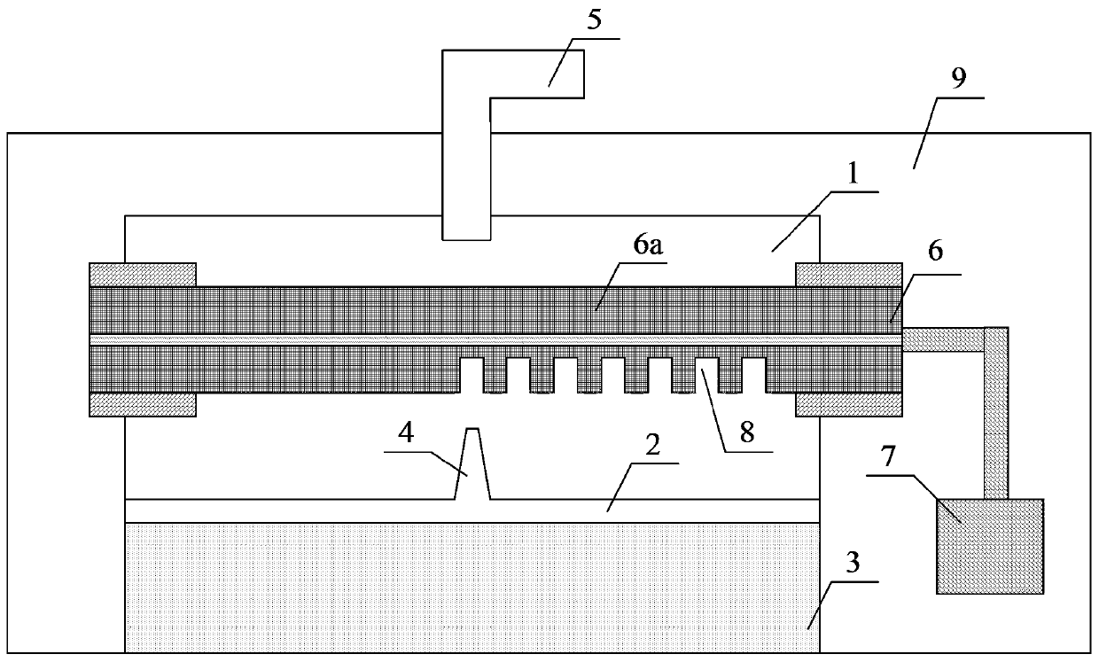
[0029] Such as figure 1 As shown, the manufacturing steps of the long-period fiber grating in this embodiment are as follows:

[0030] An airtight container 1 is arranged, and the airtight container 1 is divided into upper and lower parts by a cover plate 2, and micropores 4 with a diameter of 30 μm are arranged on the cover plate 2, and the upper and lower parts of the airtight container are connected through the micropores; in the airtight container The lower part of the lower part is filled with an etching solution 3, and an optical fiber insertion hole for inserting an optical fiber is provided on the side wall of the upper part; an air extraction hole 5 is provided on the top of the airtight container 1, directly above the microhole 4;

[0031] Specifically, mix 200mL of hydrofluoric acid solution with a mass concentration of 30% and 50mL of a glucose solution with a mass concentration of 10% as an etching solution, add it to the lower part of the airtight container 1, an...


PUM


Abstract

The invention discloses a manufacturing method for a low-cost long-period fiber bragg grating. The method is characterized by the following steps: setting a sealed container; dividing the sealed container into upper and lower parts by a cover plate; adding a corrosion solution into the lower part; forming an optical fiber insert hole in a side wall of the upper part; forming a micro-hole on the cover plate; exposing a cladding layer of an area, into which the grating is to be written, on the optical fiber; inserting into the sealed container; fixing one end of the optical fiber on a linear moveable platform; volatilizing the corrosion solution and releasing gas from the micro-hole; performing corrosion reaction between the cladding layer right above the micro-hole on the optical fiber and the gas, thereby forming a deep corrosion groove; periodically moving the horizontal position of the optical fiber by the linear moveable platform; lastly, forming periodically distributed deep corrosion grooves on the surface of the optical fiber, thereby forming the long-period fiber bragg grating. The manufacturing method for the low-cost long-period fiber bragg grating provided by the invention has the advantages of requiring no grating corrosion for mask plate and low manufacturing cost, is suitable for batch manufacturing and is suitable for various optical fibers.

Description

technical field [0001] The invention relates to a manufacturing method of a long-period optical fiber grating, in particular to a manufacturing method of a low-cost long-period optical fiber grating. Background technique [0002] Since A.M.Vengsarkar and others successfully wrote the Long Period Fiber Grating (LPFG) structure in the optical fiber for the first time in 1995, LPFG technology has been developed and applied rapidly, especially in the field of optical fiber sensing, because LPFG has the ability to Sensitive to the external environment, simple structure, small insertion loss, easy to realize long-distance sensing and other advantages, it is widely used in the detection system of physical quantities such as pressure, strain, temperature and refractive index. [0003] At present, there are two main types of long-period fiber grating manufacturing methods: one is to use the ultraviolet photosensitive properties of photosensitive optical fibers to form a periodic grat...

Claims


Application Information

Patent Timeline
Patent Type & Authority Patents(China)
IPC IPC(8): G02B6/02
CPCG02B6/02123G02B6/02152
Inventor 徐峰魏常徐俊屿蔡长辉王元杰田春雨王振荣
Owner 安徽蓝海之光科技有限公司
Why Eureka
Try Eureka