Double-channel liquid metal magnetic fluid power generator

A magnetic fluid generator and magnetic fluid power generation technology, applied in electrical components, electromechanical devices and other directions, can solve the problems of large amount of gallium alloy and high production cost of generators, and achieve the effect of reducing the number of use, compact structure and reducing production cost.

Inactive Publication Date: 2017-01-25
中国科学院电工研究所无锡分所
View PDF9 Cites 6 Cited by
  • Summary
  • Abstract
  • Description
  • Claims
  • Application Information

AI Technical Summary

Problems solved by technology

[0005] The purpose of the present invention is to provide a dual-channel liquid metal magnetic fluid generator, which can reduce the amount of gallium alloy by optimizing the structure of the generator, thereby reducing the

Method used


Image

  • Double-channel liquid metal magnetic fluid power generator
  • Double-channel liquid metal magnetic fluid power generator
  • Double-channel liquid metal magnetic fluid power generator

Examples


Embodiment 1

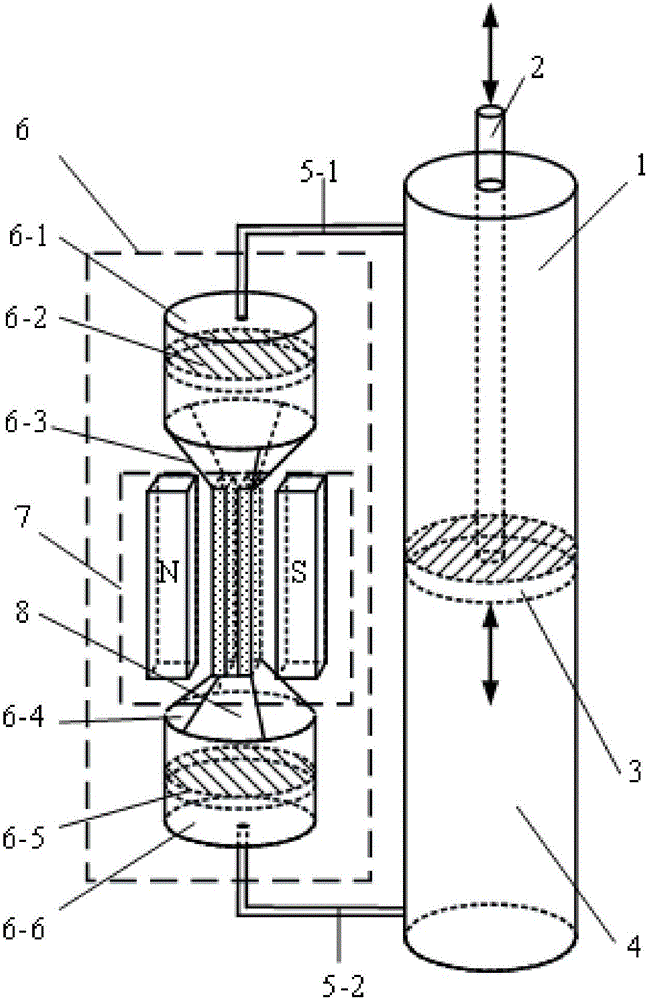
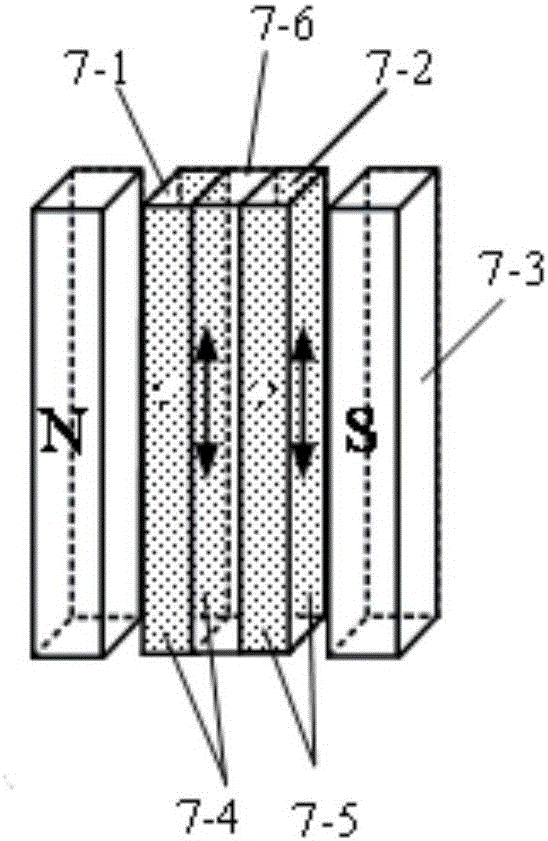
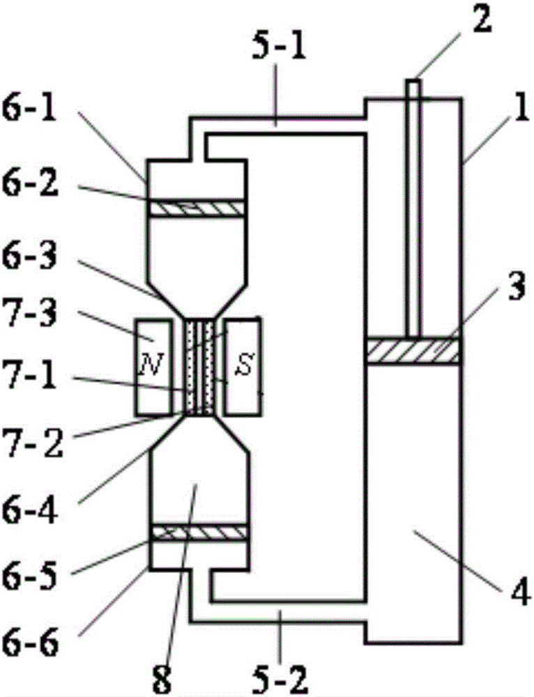
[0027] see Figure 1 to Figure 3 As shown, in this embodiment, a dual-channel liquid metal magnetic fluid generator includes a main hydraulic cylinder 1, a main piston rod 2, a main piston 3, hydraulic oil 4, an upper connecting pipe 5-1, and a lower connecting pipe 5-2 Composed of a set of power generation unit 6, the power generation unit 6 includes an upper piston cylinder 6-1, an upper piston 6-2, an upper transition section 6-3, a lower transition section 6-4, a lower piston 6-5, a lower piston cylinder 6-6 and an effective magnetic fluid power generation section 7, the effective magnetic fluid power generation section 7 includes a first magnetic fluid power generation channel 7-1, a second magnetic fluid power generation channel 7-2, a magnet 7-3, and a pair of first plate electrodes 7-4. The second plate electrode pair 7-5 and the insulating plate 7-6.

[0028] The first magnetic fluid power generation channel 7-1 and the second magnetic fluid power generation channel ...

Embodiment 2

[0038] see Figure 4 As shown, the dual-channel liquid metal magnetic fluid generator of this embodiment and the first embodiment has an equivalent power generation effect. In the form of the unit, the two generating units are symmetrically arranged, which include the main hydraulic cylinder 1, the main piston rod 2, the main piston 3, the hydraulic oil 4, the first upper connecting pipe 5-1-1, and the first lower connecting pipe 5-2 -1. The second upper connection pipe 5-1-2, the second lower connection pipe 5-2-2, the first power generation unit and the first power generation unit, the two ends of the first power generation unit and the second power generation unit are respectively It is symmetrically connected to the main pipe through the first upper connecting pipe 5-1-1, the first lower connecting pipe 5-2-1, the second upper connecting pipe 5-1-2 and the second lower connecting pipe 5-2-2. on hydraulic cylinder 1.

[0039] The first power generation unit includes a fir...


PUM

PropertyMeasurementUnit
Melting pointaaaaaaaaaa

Abstract

The invention discloses a double-channel liquid metal magnetic fluid power generator. The double-channel liquid metal magnetic fluid power generator comprises a main hydraulic cylinder assembly and at least one set of power generation unit, wherein each power generation unit comprises an upper piston assembly, an upper transition section, a lower transition section, a lower piston assembly and an effective magnetic fluid power generation section; each upper piston assembly and each lower piston assembly are respectivelycommunicated with a main cylinder through an upper connecting pipe and a lower connecting pipe; each effective magnetic fluid power generation section comprises a first magnetic fluid power generation channel, a second magnetic fluid power generation channel, a magnet, a first electrode pair, a second electrode pair and an insulation plate; a sealed communicating space filled with liquid metal is formed among each upper piston assembly, each upper transition section, each first magnetic fluid power generation channel, each second magnetic fluid power generation channel, each lower transition section and each lower piston assembly. The double-channel liquid metal magnetic fluid power generator has the advantages that the manufacturing cost of the power generator is reduced, the usage amount of magnets is reduced, the weight and size of the power generator are further reduced, and the structure of the power generator is more compact.

Description

technical field [0001] The invention relates to a power generating device, in particular to a dual-channel liquid metal magnetic fluid generator. Background technique [0002] The new Liquid Metal Magnetohydrodynamics (LMMHD) generator uses alternating external forces, such as automobile internal combustion force and wave force, to directly drive the liquid metal to reciprocate and linearly move in the power generation channel, cut the magnetic field lines, and generate AC power. Compared with the traditional LMMHD power generation system, such as two-phase flow power generation system and single-phase flow power generation system, the new LMMHD generator adopts direct drive and single-phase liquid metal power generation working fluid, without additional energy and equipment to maintain a good working fluid Conductivity, simple structure, high power density, and high efficiency, so it has broad application prospects in hybrid electric vehicles, distributed power supplies, an...

Claims


Application Information

Patent Timeline
IPC IPC(8): H02K44/08
CPCH02K44/085
Inventor 彭爱武刘艳娇赵凌志刘洣娜张新忠
Owner 中国科学院电工研究所无锡分所
Why Eureka
Try Eureka