
Miniature carrying device driven by liquid metal

A liquid metal and carrier technology, applied in the field of microfluidics, can solve the problems of micro carrier or high processing cost, poor flexibility, etc., and achieve the effect of simple structure and low cost

Active Publication Date: 2017-02-01
TSINGHUA UNIV
View PDF4 Cites 17 Cited by
  • Summary
  • Abstract
  • Description
  • Claims
  • Application Information

AI Technical Summary

Problems solved by technology

The existing mechanical handling structure requires the use of rigid structures such as gears and screws, which is less flexible. In addition, in the design of micro-carriers, due to the scale of machining, it is often impossible to realize miniature carriers or the processing costs are high.

Method used


Image

  • Miniature carrying device driven by liquid metal
  • Miniature carrying device driven by liquid metal

Examples


Embodiment 1

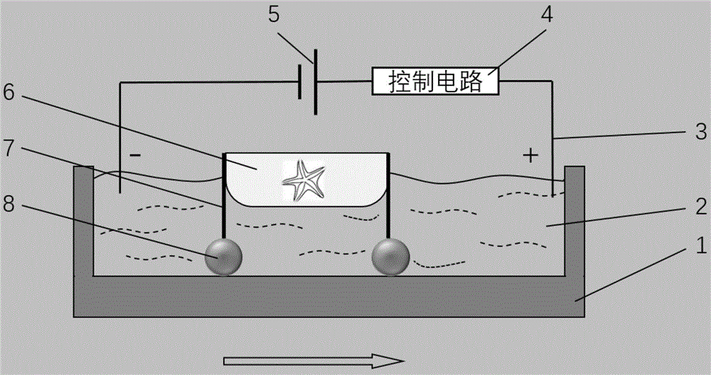
[0019] figure 1 It is a schematic side view of a liquid metal-driven micro carrier device driven by an external power supply and a control circuit according to the present invention. The electrolyte solution 2 is placed in the container 1 , and the micro carrier device includes a carrier structure 6 , an attachment structure 7 and a liquid metal wheel 8 . The carrying structure 6 is a 3D printed boat-shaped plastic structure floating on the surface of the electrolyte 2 . The attachment structure 7 is a copper rod with a diameter of 1mm, the upper end is bonded to the carrying structure 6 by glue, and the lower end is connected to the liquid metal wheel 8 through infiltration. The liquid metal wheel 8 is immersed in the electrolyte 2 . In this embodiment, the electrolyte 2 is a sodium hydroxide solution with a concentration of 0.5 mol / L. The control circuit 4 is connected to the power supply 5 and is located outside the container 1. The electrode 3 is extended through the co...

Embodiment 2

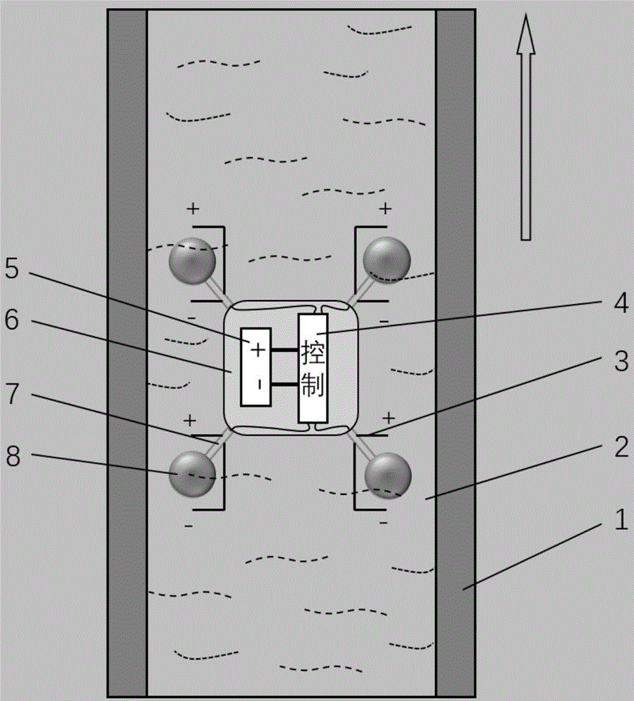
[0021] figure 2 It is a top view schematic diagram of a liquid metal-driven micro carrier device proposed by the present invention driven by a built-in power supply and control circuit. The container 1 is a channel, and the electrolyte 2 is placed in the channel. The micro-carrier includes a carrier structure 6, an attachment structure 7, and four liquid metal wheels 8. The carrier structure 6 is a 3D-printed boat-shaped plastic structure that floats on the surface of the electrolyte 2. On the surface. Electrolyte 2 is a 0.2 mol / L hydrochloric acid solution. The attachment structure 7 is a copper rod with a diameter of 1.2 mm. One end is glued to the carrying structure 6 by glue, and the other end is connected to the liquid metal wheel 8 by wetting. The non-contact end of the copper rod is attached with insulating varnish. The liquid metal wheel 8 is immersed in the electrolyte 2 . The control circuit 4 is connected to the power supply 5 and located inside the carrying str...


PUM


Abstract

A miniature carrying device driven by liquid metal comprises a carrying structure connected with an adhesion structure. Liquid metal wheels are connected to the adhesion structure through immersion. The liquid metal wheels are immersed in an electrolyte, when a power source acts on the electrolyte, an electric field is formed in the electrolyte, the liquid metal wheels can be driven to move, the carrying structure is then pulled, a control circuit can be used for generating different magnitudes of force on the different liquid metal wheels, and thus the miniature carrying device moves forwards and backwards or turns. The miniature carrying device has the characteristics of simple structure and low cost. By means of the design of different carrying structures and regulation of the injection amount of the liquid metal wheels, miniature carrying devices in different sizes can be obtained. Meanwhile, the liquid metal wheels have the characteristic of flexibility and can deform and restore into the original shapes when bearing external force, and thus the liquid metal wheels cannot get stuck or suffer from structural damage due to collision when operating in tracks. The miniature carrying device can be applied to the fields of microfluid, biological chips, micro-robots and the like.

Description

technical field [0001] The invention belongs to the field of microfluid technology, in particular to a liquid metal-driven micro-carrying device. Background technique [0002] Liquid metal is a metal material with a melting point in the room temperature range, which exhibits solid metal properties at low temperatures and liquid states at normal or high temperatures. Liquid metals are usually dominated by gallium metal and its alloys, including gallium-indium alloys and gallium-indium-tin alloys. It has good electrical and thermal conductivity, metallic luster, good fluidity and surface tension in a liquid state. Liquid metal has certain wettability, and liquid metal ink can be used to make flexible mechanical sensors, or electronically printed circuits. It can also be combined with its conductivity and flow properties to make an electromagnetic pump that can be directly driven by electricity. In recent years, Liu Jing’s research team at Tsinghua University has discovered ...

Claims


Application Information

Patent Timeline
Patent Type & Authority Applications(China)
IPC IPC(8): B25J7/00
CPCB25J7/00
Inventor 姚又友刘静
Owner TSINGHUA UNIV
Learn More