Ice source heat pump system

A heat pump system, ice source technology, applied in lighting and heating equipment, heating and cooling combination, compressor with reversible cycle, etc., can solve the problems of low cooling and heating efficiency, poor heat dissipation, and easy frosting of the evaporator , to achieve the effect of high cooling and heating efficiency, excellent system structure and well-configured components

Inactive Publication Date: 2017-02-01
重庆鸿佳新科技有限公司
View PDF7 Cites 4 Cited by
  • Summary
  • Abstract
  • Description
  • Claims
  • Application Information

AI Technical Summary

Problems solved by technology

The air source heat pump air conditioning system and the water source heat pump air conditioning system are the most used at present, but these two air conditioning systems have technical defects. If the outside temperature of the air source heat pump air conditioning system is lower than 5°C, the surface temperature of the heat transfer tube is lower than 0°C , the moisture in the air will frost on the surface of the heat transfer tube, and as the frost thickens, it will block the air flow channel, significantly reducing the heat absorbed by the heat pump working fluid from the air through the evaporator, resulting in the failure of the air source heat pump. Reduced heating coefficient and operational reliability
The air source heat pump needs to defrost regularly, which not only consumes a lot of energy, but also affects the normal operation of the air conditioning system; at the same time, when the air source heat pump air conditioner is cooling in summer, with the increase of the outdoor ambient temperature, the condensation temperature is higher than 50 ℃, The cooling coefficient decreases accordingly, and the energy efficiency decreases, which is 50% lower than that of the water-cooled chiller; while the water source heat pump air conditioning system has a water freezing point of 0°C, in order to ensure that the exchanger will not be damaged by freezing, and in order to ensure the safety of the equipment, the water source in winter The temperature must be above 8°C before it can be used, and the water source heat pump air conditioning system needs to lay a large number of pipes underground during installation, so the cost is quite high. The cooling load in the south far exceeds the heating load, and the heating load in the north is far greater than the cooling load. The cooling and heating loads are unbalanced. Year after year, the buried pipe water source heat pump will eventually make the underground temperature of the project in the southern region higher and higher, and the heat dissipation will become higher and higher. As a result, the energy efficiency of water source heat pumps in this area is gradually reduced when summer cooling is most needed, and the underground temperature of projects in northern areas will be lower and lower, and heat absorption will become worse, resulting in the energy efficiency of water source heat pumps in this area when winter heating is most needed. Reduced, as the years go by, eventually this costly energy-saving system may be paralyzed, and there is also the risk of geological variation
[0003] In order to solve the problems of easy frosting and low cooling and heating efficiency of the existing heat pump system evaporator, the applicant submitted an ice source air exchanger on December 15, 2015, which includes heat dissipation filler, fan and ice source solution The effusion pool, the heat dissipation filler is filled in the filling chamber, the fan is fixed at the air outlet of the casing, the ice source solution effusion pool is installed in the casing through the support frame and is located directly below the filling chamber, and the ice source solution effusion pool passes through The pipeline is connected with a circulating water pump, and the outlet end of the circulating water pump is connected with a spray pipe, which is installed on the top of the filling chamber. The spray pipe sprays the ice source solution into the filling chamber, and the lower end of the filling chamber is provided with a Solution outlet connected to effusion pool

Method used


Image

  • Ice source heat pump system

Examples


Embodiment Construction

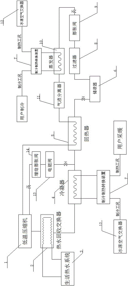
[0022] Such as figure 1 As shown, the system includes a compressor 1, a condenser 4, a liquid receiver 6, a filter 8, a throttling device 9, an evaporator 10, and a gas-liquid separator 11. The throttling device of this embodiment adopts an expansion valve 9, and the compression The function of machine 1 is to turn the refrigerant into high-temperature and high-pressure refrigerant vapor, and deliver the high-temperature and high-pressure gas to the condenser 4, and after being condensed by the condenser 4, it passes through the liquid receiver 6, the filter 8 and the expansion valve 9 to enter the evaporator 10. After being evaporated by the evaporator 10, it is returned to the compressor 1 by the gas-liquid separator 11. The refrigerant liquid condensed by the condenser 4 is stored in the accumulator 6, and the refrigerant in the accumulator 6 enters the evaporator 10 after being filtered and throttled, and the evaporator absorbs the heat of the air in the room to achieve co...


PUM


Abstract

The invention provides an ice source heat pump system. The ice source heat pump system comprises a compressor, a condenser, a regenerator, a liquid storage device, a filter, a throttle device, an evaporator and a gas-liquid separator, wherein an ice source air interchanger is connected to the condenser and the evaporator by virtue of a refrigeration and heating conversion device, a first inlet of the regenerator is connected with an outlet of the condenser, a first outlet of the regenerator is connected with an inlet of the liquid storage device, a second inlet of the regenerator is connected with an outlet of the gas-liquid separator, a second outlet of the regenerator is connected with an inlet of the compressor, and an enthalpy adding expansion valve is arranged between an outlet of the condenser and the inlet of the compressor. An ice source aqueous solution which cannot freeze at 30 DEG C below zero is added to the ice source air interchanger, so that the system can be prevented from being frosted when heat exchange is performed in heating conditions, and the heating efficiency of the system is stable; additionally, the ice source heat pump system has the advantages of large energy saving amplitude, wide application range, no limit to geographic positions or weather conditions and good energy saving transformation versatility and is applicable to various places at 30 DEG C below zero to 50 DEG C.

Description

technical field [0001] The invention belongs to the technical field of heat pump systems, in particular to an ice source heat pump system. Background technique [0002] At present, with the rapid growth of the world's population and economy, energy consumption has increased dramatically. Today, with the increasingly serious environmental pollution and the destruction of the living environment, people's desire to be green and protect the environment is becoming stronger and stronger. Nowadays, air conditioners are basically used in every household. With the use of air conditioners, the power consumption increases sharply. Therefore, various new air conditioning systems have emerged to solve the problem of increased power consumption. The air source heat pump air conditioning system and the water source heat pump air conditioning system are the most used at present, but these two air conditioning systems have technical defects. If the outside temperature of the air source hea...

Claims


Application Information

Patent Timeline
Patent Type & Authority Applications(China)
IPC IPC(8): F25B29/00F25B13/00F25B41/04F25B41/06F25B41/20F25B41/31
CPCF25B13/00F25B29/003F25B2400/19F25B2313/02741F25B41/31F25B41/20
Inventor 李开年曾斌
Owner 重庆鸿佳新科技有限公司
Why Eureka
Try Eureka