Electric smelting forming method for nuclear power plant evaporator barrel body

A technology for evaporators and nuclear power plants, applied in welding equipment, metal processing equipment, manufacturing tools, etc., can solve problems affecting the mechanical properties of materials, complicated processes, and difficult control of chemical and mechanical properties, and achieve outstanding corrosion resistance and other properties. The effect of simplifying the processing procedure and shortening the product cycle

Inactive Publication Date: 2017-02-08
NANFANG ADDITIVE MFG TECH
View PDF7 Cites 2 Cited by
  • Summary
  • Abstract
  • Description
  • Claims
  • Application Information

AI Technical Summary

Problems solved by technology

This method is widely used in production and can also meet the quality requirements, but for the gradually increasing demand for material components, forging, especially heat treatment, is prone to problems such as very uneven macroscopic material phase structure. The process is complex, chemical and It is difficult to control the mechanical properties, which also leads to poor quality stability and high scrap rate. At the same time, from the final grain measurement results of the process, it is generally only about 5-7 grades, which is expected to be further refined in the current R&D and production. Granules are used to improve the mechanical properties, especially the comprehensive performance of strength and toughness. This process has a big bottleneck.
[0005] In addition, the method of segmented material forging and tailor welding used in the evaporator equipment also severely splits the continuous direction of the mechanical fibers due to the increase in the weld seam, which greatly affects the mechanical properties of the material and the safety of the container equipment. And it is also very easy to cause the delay of the manufacturing period and increase the cost.

Method used


Image

  • Electric smelting forming method for nuclear power plant evaporator barrel body
  • Electric smelting forming method for nuclear power plant evaporator barrel body
  • Electric smelting forming method for nuclear power plant evaporator barrel body

Examples


Embodiment Construction

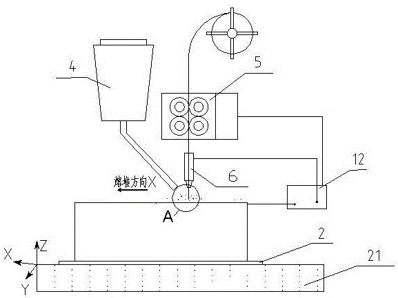
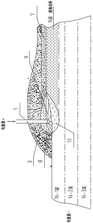
[0021] Specific embodiments of the present invention will be described below with reference to the accompanying drawings. figure 1 It is a schematic diagram for illustrating the electrofusion forming method in the specific embodiment; figure 2 for figure 1 Partial enlarged view near the location shown in A. Since it is a schematic diagram, the components in the diagram are schematic, and their actual shapes and dimensions are not limited by the diagram.

[0022] The forming method is to melt the raw material 1 layer by layer ( figure 1 Shown in the state when it is deposited to the Nth layer) is deposited on the base material 2, thereby finally forming the desired metal member.

[0023] The specific implementation process is:

[0024] A. The wire feeding mechanism 5 sends the raw material wire 1 to the surface of the base material 2 placed on the workbench 21 , which is covered with the granular auxiliary materials conveyed by the powder feeding mechanism 4 .

[0025] B...


PUM

PropertyMeasurementUnit
diameteraaaaaaaaaa
lengthaaaaaaaaaa
diameteraaaaaaaaaa

Abstract

The invention provides an electric smelting forming method for a nuclear power plant evaporator barrel body. According to the electric smelting forming method, a high energy heat source formed by combining electric arc heat, electric resistance heat and electric slag heat is used for smelting continuously conveyed metal raw material wires, and metal components are formed and manufactured through layer-by-layer solidification and accumulation on a substrate; and a computer is used for controlling the relative movement of an electric smelting head and the substrate, rapid cooling and layer-by-layer solidification and accumulation of a molten pool on the substrate are realized, and finally the nuclear power plant evaporator barrel body is formed. The electric smelting forming method for the nuclear power plant evaporator barrel body has the advantages of high efficiency, low cost, good mechanical performance and the like.

Description

technical field [0001] The invention relates to an electromelting forming method for an evaporator cylinder body of a nuclear power plant. Background technique [0002] The steam generator is one of the core equipment in the primary circuit system of a nuclear power plant. It is the key component for the cooling water of the secondary circuit to be evaporated into steam after heat exchange with the high-pressure water of the primary circuit to drive the steam turbine to do work to realize power generation. It is also the hub of heat conversion between the primary and secondary circuits. In the nuclear power primary circuit system, the evaporator equipment is the heaviest (the total weight of a typical AP1000 vessel is 600 tons), and the largest size (the diameter of the upper vessel section of the AP1000 is more than 5 meters, and the total height of the vessel is more than 20 meters), plus the harsh working environment and The increasingly extreme safety requirements, so th...

Claims


Application Information

Patent Timeline
Patent Type & Authority Applications(China)
IPC IPC(8): B23K28/02
CPCB23K28/02
Inventor 张国春余征汤海波刘栋
Owner NANFANG ADDITIVE MFG TECH
Why Eureka
Try Eureka