
Shed tunnel and shed tunnel design method

A design method and shed-hole technology, applied in protective equipment, buildings, etc., can solve problems such as high stiffness, overall structural damage, and long construction period.

Active Publication Date: 2017-02-15
INST OF MOUNTAIN HAZARDS & ENVIRONMENT CHINESE ACADEMY OF SCI
View PDF7 Cites 6 Cited by
  • Summary
  • Abstract
  • Description
  • Claims
  • Application Information

AI Technical Summary

Problems solved by technology

Its technical defects are manifested in: firstly, because the rolling stones are blocked from draining down and silted up on the roof of the cave, the load borne by the roof under the action of "large-scale mass" rolling stones continues to increase, which directly reduces the structural safety
Secondly, this type of structure is mainly designed based on the theory of "force control", with relatively high rigidity, which can directly block the impact of "high-speed and high-strength" rolling stones. "Rolling stones cause continuous damage, and finally when the damage accumulates to a certain extent, there will be systematic and sudden damage without warning, which is extremely harmful
Finally, the traditional barrier-type sheds are mostly reinforced concrete structures, which have high construction costs, long construction periods, difficulty in building in alpine and canyon areas, difficult repairs after damage, and unfavorable factors such as increased bridge and tunnel loads due to their own weight. canyon area application

Method used


Image

  • Shed tunnel and shed tunnel design method
  • Shed tunnel and shed tunnel design method
  • Shed tunnel and shed tunnel design method

Examples


Embodiment 1

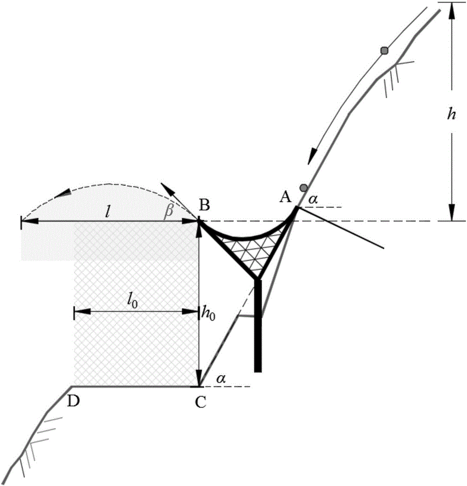
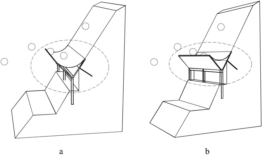
[0110] As shown in the figure, a kind of shed hole is processed and installed, which is arranged between the roadbed in the mountainous area and the slope of the mountain to prevent the rolling stones on the slope from harming the roadbed. The road is located in Kangding County, Ganzi Tibetan Autonomous Prefecture, Sichuan. When it crosses Zheduo Mountain, it is forced to develop along a section of high and steep slope in Guzan Town due to the large slope drop. The slope in this section is high in altitude, low in temperature, and develops freeze-thaw collapses at the top of the mountain. Rolling stone disasters have the characteristics of "multiple points", "wide area" and "frequent high-level occurrences", which cause serious harm to road traffic safety and need to be dealt with urgently.

[0111] figure 1 It is a side view of the installation position of the shed hole, image 3 a. image 3 b is a three-dimensional schematic diagram of the installation position of the shed...

Embodiment 2

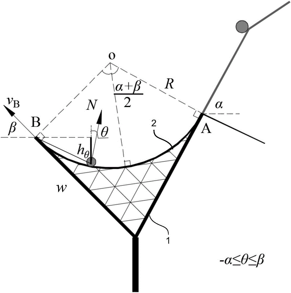
[0117] Adopt the design method of the present invention to complete the design of the shed hole in Embodiment 1, determine the value R of the curvature radius of the cover plate, and the buried depth value L of the column of the grouted steel pipe pile structure p , Anchorage depth value L in the anchorage system b parameter design.

[0118] After investigation, the road section endangered by landslides and rolling rocks is 1.2km long, and the effective width of the safe airspace of the roadbed to be controlled is l 0 = 10m, effective height h 0 = 6m. The inclination angle of the inner slope of the road is α=55°, and the collapse mainly occurs in the seasonal ice and snow-covered belt near the elevation of 250m above the road, resulting in a fall height from h min = 150m to h max = 300m are distributed collapse rolling stone groups. The rolling stone particles are uniformly small as a whole, with a particle size of about 0.1m and a maximum of 0.5m, corresponding to the ma...

Embodiment 3

[0128] The main structure design of the truss structure ceiling is completed on the basis of the second embodiment.

[0129] Figure 8 Is the schematic diagram of the truss structure ceiling. The truss structure ceiling includes a rigid ring beam 121 for fixing the cover plate, a vertical truss triangular surface 122 connected under the rigid ring beam 121, a transverse main beam 123 perpendicular to the vertical truss triangular surface 122, necessary side frames, and auxiliary beams.

[0130] Figure 9 It is a cross-sectional structure diagram of a monolithic truss ceiling. The angle at the bottom of the triangular surface 122 of the vertical truss = π - (α + β) = 100°, and the length of the side frames 124 on both sides of the triangular surface 122 of the vertical truss is determined according to formula 2:


PUM


Abstract

The invention provides a shed tunnel structural body. By adoption of the shed tunnel structural body, the defects that the control effect of existing wall type, arch type, cantilever type and column type shed tunnel structures or other shed tunnel structures on high-speed and high-impact rolling stones breaking out in large-scale and grouped modes is limited, the construction cost is high, and the applicability is poor are solved. A shed tunnel is arranged between a roadbed and a mountain slope in a mountainous area, and comprises a Y-shaped frame beam. The top of the Y-shaped frame beam is connected with a downward-concave arc-shaped cover plate. The fixed side edge of the cover plate is tangent to the mountain slope, and the included angle beta between the tangent line of the top end of the free side edge of the cover plate and the horizontal plane is smaller than or equal to 45 degrees. The cover plate of the shed tunnel is of a sandwich structure which is formed by filling the space between an upper skin plate and a lower skin plate with energy dissipating materials. The invention further provides a shed tunnel design method. The shed tunnel design method is used for designing the curvature radius value R of the cover plate, the burial depth value Lp of a structural stand column of a grouted steel pipe pile of the shed tunnel, and the anchor depth values Lb of the side edges of the cover plate of the shed tunnel. According to the shed tunnel, a novel skid-jumping self-throwing removal and guide technical concept is adopted, and the shed tunnel has advantages on the aspect of preventing impact damage of high-altitude rolling stones on the slope to a road. The shed tunnel is simple in structure and high in environment adaptability.

Description

technical field [0001] The invention relates to a shed cave and a design method thereof, in particular to a structure and a design method thereof for preventing and controlling high-speed slope disasters on the inner side of mountainous roads, and belongs to the fields of disaster prevention and control in mountainous areas and road and bridge engineering. Background technique [0002] When the main road passes through the mountains and valleys, the subgrade is often cut and excavated from the more stable side of the slope, and most of them are high-level subgrades on the slope. This kind of bridge project is located in a special geological and landform environment, especially the high-speed slope rock disaster caused by the middle / high collapse, which often smashes vehicles and blocks traffic, seriously affecting economic and social development. Especially on the main traffic lines in the western mountainous area, the disaster of landslides and rolling rocks is serious, and...

Claims


Application Information

Patent Timeline
IPC IPC(8): E01F7/04
CPCE01F7/045Y02A10/23
Inventor 吴永李新坡何思明罗渝王东坡
Owner INST OF MOUNTAIN HAZARDS & ENVIRONMENT CHINESE ACADEMY OF SCI
Learn More