
Airborne detecting device for laser remote sensing of gas leakage

A detection device, a technology for gas leakage, which is applied in measurement devices, gas/liquid distribution and storage, mechanical equipment, etc., can solve problems such as phase change, leakage, and error, and achieve the goal of improving accuracy, eliminating errors, and eliminating leakage detection. Effect

Inactive Publication Date: 2017-02-15
HEFEI INSTITUTES OF PHYSICAL SCIENCE - CHINESE ACAD OF SCI
View PDF9 Cites 6 Cited by
  • Summary
  • Abstract
  • Description
  • Claims
  • Application Information

AI Technical Summary

Problems solved by technology

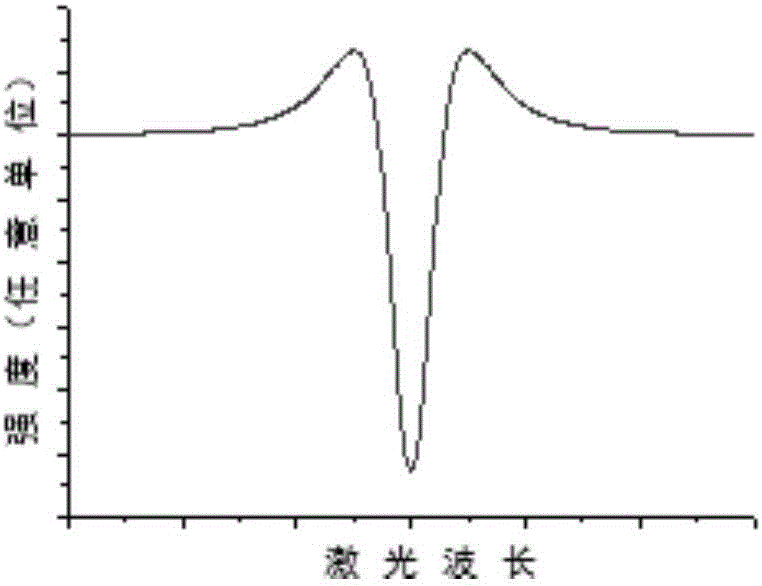
This detection system and method, which uses the ratio of the residual amplitude of the second harmonic signal to the first harmonic signal to eliminate the influence of light intensity, has achieved some effects, but there are still deficiencies. First, due to the demodulation of the second The harmonic signal and the first harmonic signal use different lock-in amplifiers, and the information such as the phase of the two lock-in amplifiers is not consistent, and the distance of remote sensing detection technology changes in practical applications, which causes the phase to change. There are certain changes, which will cause a large error in eliminating the influence of light intensity fluctuations by using the ratio of the second harmonic signal to the residual amplitude of the first harmonic signal; secondly, the distance that the detection system moves in unit time is limited, Difficult to quickly and efficiently detect leaks in large regional natural gas pipeline networks

Method used


Image

  • Airborne detecting device for laser remote sensing of gas leakage
  • Airborne detecting device for laser remote sensing of gas leakage
  • Airborne detecting device for laser remote sensing of gas leakage

Examples


Embodiment Construction

[0020] The preferred modes of the present invention will be further described in detail below in conjunction with the accompanying drawings.

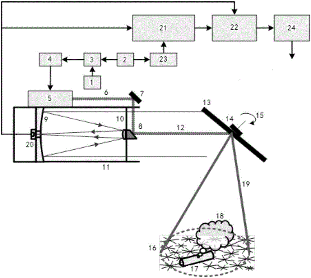
[0021] see figure 1 , the gas leak laser remote sensing airborne detection device consists of the following:

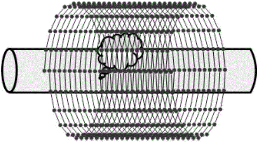
[0022] The device is located on the aircraft, and it includes an electrically connected infrared laser emitting part, an infrared laser receiving part and a control processing part, as well as a spiral detection track part; wherein,

[0023] The infrared laser emitting part is a laser 5, a first reflector 7 and a second reflector 8 positioned on the optical axis 12 of the light collector 11 which are optically connected in turn; the laser 5 wherein is a narrow linewidth diode laser (which can be a narrow linewidth quantum cascade lasers, or narrow linewidth CW OPO lasers).

[0024] The infrared laser receiving components are a light collector 11 and a detector 20 located at the focal point of the light collector 11; wherein t...


PUM


Abstract

The invention discloses an airborne detecting device for laser remote sensing of gas leakage. The airborne detecting device comprises an infrared laser transmitting part, an infrared laser receiving part and a controlling and processing part electrically connected with the infrared laser transmitting part and the infrared laser receiving part; particularly, the airborne detecting device is located on an aircraft and also comprises a spiral detecting track part composed of a rotating reflecting mirror (13) arranged on a shaft of a motor (14), wherein the included angle formed by a normal of the rotating reflecting mirror (13) and an axis of the motor (14) is 1-6 DEG, and an angle formed by the normal of the rotating reflecting mirror (13) and an optical axis (12) of the infrared laser transmitting part is 40-50 DEG; and the controlling and processing part comprises a transmitting signal control assembly and a receiving signal processing assembly which are electrically connected, wherein the transmitting signal control assembly is used for realizing modulation for the output of a laser device (5) in the infrared laser transmitting part, and the receiving signal processing assembly is used for calculating the concentration of leaked gases according to the detected signals carrying leakage gas information. The airborne detecting device can be widely applied to precise location and large-area rapid detection for natural gas leakage.

Description

technical field [0001] The invention relates to a laser remote sensing airborne detection device, in particular to a laser remote sensing airborne detection device for gas leakage. Background technique [0002] With the continuous expansion of natural gas consumption, my country has built hundreds of thousands of kilometers of natural gas pipelines. For such a long natural gas pipeline network, leakage is inevitable in the process of natural gas transportation, storage, and sales management, and it is also the main cause of safety accidents. Therefore, in order to find the leakage point in time, people have developed the laser remote sensing detection technology for natural gas leakage. However, when this technology detects natural gas leaks, due to the received scattered light depending on the reflector, the return light power varies greatly, and the demodulated second harmonic signal is proportional to the light intensity, so that the measurement results accuracy is grea...

Claims


Application Information

Patent Timeline
Patent Type & Authority Applications(China)
IPC IPC(8): F17D5/06G01N21/17G01M3/38
CPCF17D5/06G01M3/38G01N21/17G01N2021/1793
Inventor 高晓明汪磊梅教旭谈图
Owner HEFEI INSTITUTES OF PHYSICAL SCIENCE - CHINESE ACAD OF SCI
Learn More