
A supercritical carbon dioxide fracturing simulation experiment device

A technology for simulating experimental devices and carbon dioxide. It is used in measuring devices, using stable tension/pressure to test the strength of materials, instruments, etc. It can solve the problems of insufficient understanding of the expansion mechanism and difficulty in directly observing the crack shape, so as to increase crack expansion. The effect of form range, convenient operation, easy disassembly and assembly

Active Publication Date: 2019-11-12
CHINA UNIV OF PETROLEUM (BEIJING)
View PDF7 Cites 2 Cited by
  • Summary
  • Abstract
  • Description
  • Claims
  • Application Information

AI Technical Summary

Problems solved by technology

At present, due to insufficient understanding of the influencing factors and expansion mechanism of supercritical carbon dioxide fracturing fracture growth laws under fluid-solid coupling conditions, it is difficult to directly observe the actual fracture shape produced by supercritical carbon dioxide fracturing, and most people use an oversimplified two-dimensional Or the 3D model simulates the supercritical carbon dioxide fracturing process to guide the fracturing operation on site, but the results obtained are quite different from the actual ones

Method used


Image

  • A supercritical carbon dioxide fracturing simulation experiment device
  • A supercritical carbon dioxide fracturing simulation experiment device
  • A supercritical carbon dioxide fracturing simulation experiment device

Examples


Embodiment Construction

[0023] In order to have a clearer understanding of the technical features, purposes and effects of the present invention, the specific implementation manners of the present invention will now be described with reference to the accompanying drawings.

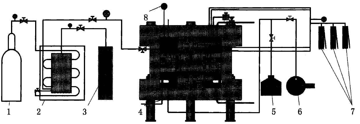
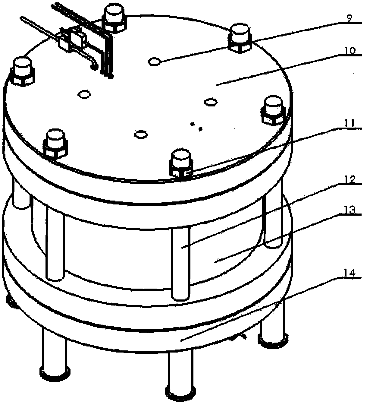
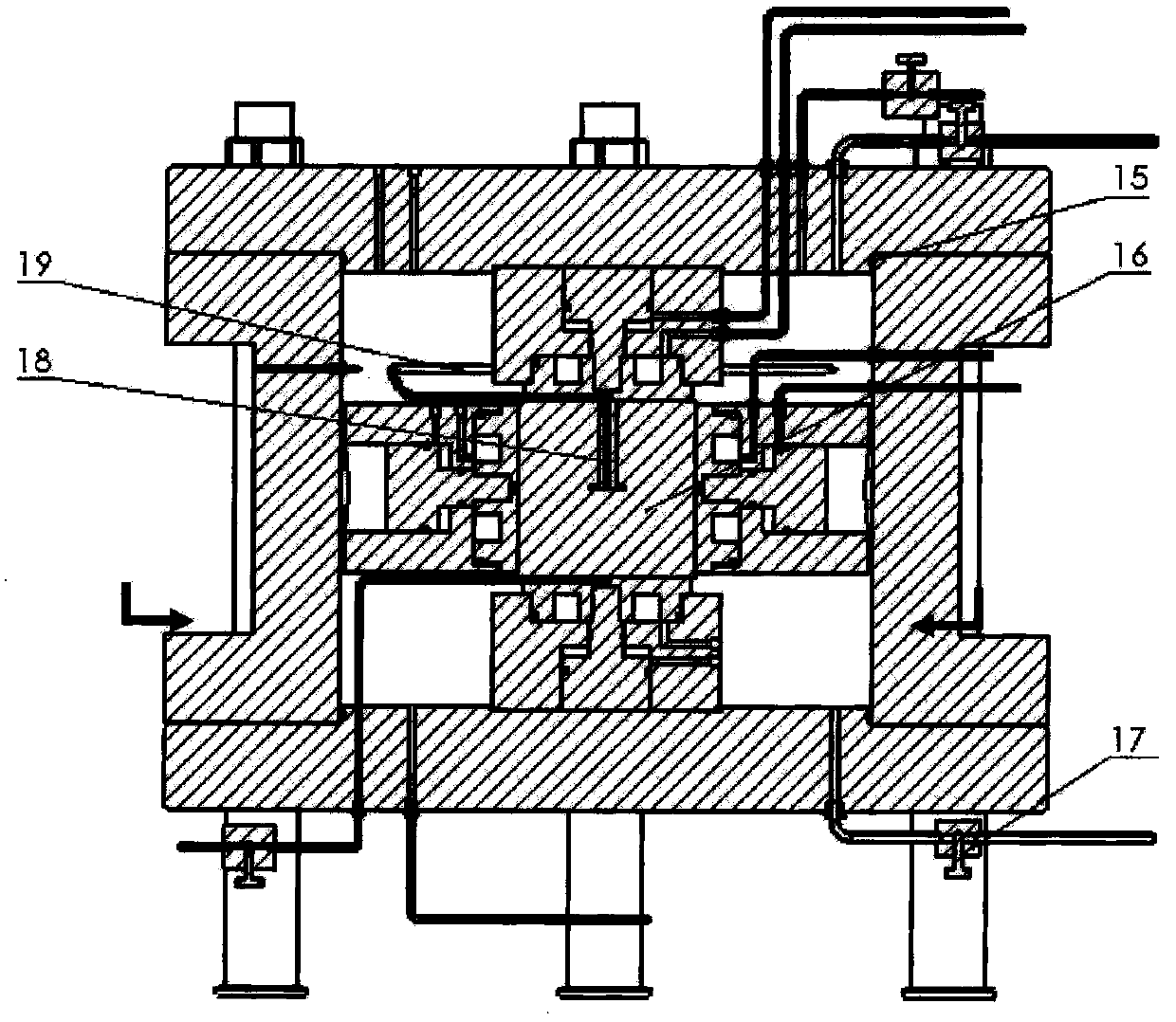
[0024] figure 1 It is an overall system diagram of the supercritical carbon dioxide fracturing simulation experiment device of the present invention; figure 2 It is a diagram of the supercritical carbon dioxide fracturing simulation experiment device of the present invention; image 3 It is a schematic cross-sectional diagram of a supercritical carbon dioxide fracturing simulation experiment device; Figure 4 It is a structural schematic diagram of the loading confining pressure device of the present invention; Figure 5 It is a schematic diagram of the unfolded structure of the flat jack of the present invention.

[0025] Such as figure 1 As shown, a supercritical carbon dioxide fracturing simulation experiment device is ch...


PUM


Abstract

The invention discloses a supercritical carbon dioxide fracturing simulation experiment device. The device is characterized in that a pressure chamber, a vacuum saturation system and a carbon dioxide phase state transformation system are included; the pressure chamber comprises a closed cavity, flat jacks and heating rods, wherein the closed cavity is composed of an upper cover plate, a confining pressure barrel and a pressure chamber base which are sealed through a seal ring, the four flat jacks are evenly distributed on the side wall of the confining pressure barrel, the upper cover plate and the pressure chamber base are each fixedly provided with one flat jack, and the heating rods are fixed to the pressure chamber base; the vacuum saturation system comprises a vacuum pump and a saturation hydraulic station; the carbon dioxide phase state transformation system comprises a carbon dioxide gas source, a cooling device and an injection pump, and carbon dioxide is liquefied by lowering the temperature and then transformed to be in a supercritical state through pressurizing and temperature increasing. According to the supercritical carbon dioxide fracturing simulation experiment device, a supercritical carbon dioxide fracturing simulation experiment is conducted on rock and an artificial test piece under the saturated pore pressure condition, the parameters such as the injection pressure, the temperature and the output volume of fracturing fluid in the fracturing process are monitored in real time, a fracture extension rule is acquired, and the device is an experimental platform for researching the supercritical carbon dioxide fracturing mechanism.

Description

technical field [0001] The invention belongs to the field of hydraulic fracturing simulation experiments, in particular to a supercritical carbon dioxide fracturing simulation experiment device. Background technique [0002] The hydraulic fracturing process consumes a large amount of water resources. The anhydrous fracturing technology basically does not use water, which relieves the pressure on the demand for water resources. At present, it has not been widely used in China. Conventional fracturing fluids contain water or various chemical reagents, and the residues cause damage to fracture permeability, thereby reducing the effect of fracturing stimulation. In order to reduce the damage of conventional fracturing fluids to formations, especially low-permeability, low-pressure, and water-sensitive oil and gas reservoirs, supercritical carbon dioxide fracturing technology has emerged. Due to its combination of fluidity of gas and high density of liquid, supercritical carbon ...

Claims


Application Information

Patent Timeline
Patent Type & Authority Patents(China)
IPC IPC(8): G01N3/12G01N3/02
CPCG01N3/02G01N3/12
Inventor 张广清吕延军周大伟
Owner CHINA UNIV OF PETROLEUM (BEIJING)
Learn More