Inductor warm-pressing forming method and inductor prepared by using same

A technology of warm pressing and compression molding, which is applied in the manufacture of inductors/transformers/magnets, components of transformers/inductors, circuits, etc. It can solve problems such as low production efficiency, high energy consumption per unit of production, and affect applications, and achieve heating The effect of short time, few appearance defects and uniform heating

Active Publication Date: 2017-02-15
KUNSHAN CITONG NEW MATERIAL TECH CO LTD
View PDF9 Cites 9 Cited by
  • Summary
  • Abstract
  • Description
  • Claims
  • Application Information

AI Technical Summary

Problems solved by technology

However, the current disadvantages of this method are low production efficiency and high energy consumption per

Method used


Image

  • Inductor warm-pressing forming method and inductor prepared by using same

Examples


Embodiment 1

[0040] Embodiment 1, the granules obtained by granulation need to be molded to become an inductor core and an inductor. as attached figure 1 As shown, the mold consists of four parts:

[0041] (1) Forming mechanism

[0042]This part is composed of cavity, upper punch 1 and lower punch 2. The shape of the cavity 3 and the punch depends on the product, and can be in any shape in theory, and the usual shapes include circular ring, cylinder, cube, cuboid and the like. The cavity is the space where the metal soft magnetic powder is finally formed, and the density of the powder increases gradually under the pressure of the punch until it is finally formed.

[0043] During the powder molding process, the powder needs to overcome the friction between the powder and the mold wall, the internal friction between the powders and the pressure required for the deformation of the powder, etc. Usually it can be achieved by applying sufficient molding pressure, but because too much pressur...

Embodiment 2

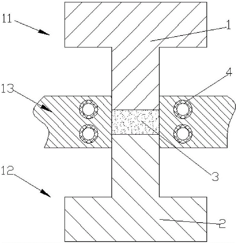
[0051] In the second embodiment, the powder obtained by granulation needs to be molded into a molded inductor. Such as figure 1 As shown, the mold consists of three parts:

[0052] (1) Forming mechanism

[0053] There are two structures of the forming mechanism, the first form will be introduced first:

[0054] This part includes an upper die 11 , a lower die 12 and a middle die 13 ; the upper die 11 includes an upper punch 1 ; the lower die 12 includes a lower punch 2 . The shape of the cavity 3 and the punch depends on the product, and can be in any shape in theory, and the usual shapes include cylinder, cube, cuboid and the like. The cavity is the space where the metal soft magnetic powder is finally formed, and the density of the powder increases gradually under the pressure of the punch until it is finally formed.

[0055] Before filling the powder, the inductance coil is first placed in the middle mold 13, and the two outgoing legs of the coil 4 are placed in the gro...


PUM


Abstract

The invention relates to an inductor warm-pressing forming method and an inductor. The inductor warm-pressing forming method comprises the steps of heating magnetic powder in a molding cavity rapidly by utilizing a changeable magnetic field of lengthways AC or ripple wave containing DC generated at the center of a molding cavity by an electrified induction coil which is arranged at the periphery of the molding cavity; then transferring heat to a binder on the surface of the magnetic powder by the heated magnetic powder to soften the binder; and performing compression molding on granulation powder which is composed of the magnetic powder and the binder to form the inductor. The inductor has high magnetic conductivity, low DC resistance and few apparent defects; and the heating time of the inductor warm-pressing forming method is short; powder is heated based on an electromagnetic induction principle; and the inductor warm-pressing forming method has advantages of high production efficiency and low energy consumption.

Description

technical field [0001] The invention relates to an inductor forming method, in particular to an inductor warm-press forming method. The invention also relates to an inductor formed by the forming method, which belongs to the technical field of processing and forming of electronic components. Background technique [0002] With the development of modern integrated circuit design and manufacturing technology, semiconductor design and manufacturing technology, robot automation manufacturing technology, electronic component technology and Internet applications, intelligence has become the mainstream technology trend of the information society and even the next generation of industrial technology revolution. At present, various DC loads (including sensors) with intelligent computing functions are rapidly transforming traditional industries and the living conditions of human beings, connecting people to people, things to things, and people to things. [0003] These complex connecti...

Claims


Application Information

Patent Timeline
IPC IPC(8): H01F41/00H01F41/02H01F27/255
CPCH01F27/255H01F41/00H01F41/0246
Inventor 郭峰黄裕茂汪贤李伟健金叶萍薛红霞周庆国
Owner KUNSHAN CITONG NEW MATERIAL TECH CO LTD
Why Eureka
Try Eureka