Defoaming device and method for electrochemical wastewater treatment system

A technology of defoaming device and treatment system, which is applied in the direction of degassed water/sewage treatment, foam dispersion/prevention, etc. It can solve the problems of incomplete elimination of defoaming device and complicated structure, so as to avoid clogging, ensure defoaming effect, Avoid the effect of water and foam seepage

Active Publication Date: 2017-02-22
SUZHOU INDAL TECH RES INST OF ZHEJIANG UNIV +2
View PDF18 Cites 8 Cited by
  • Summary
  • Abstract
  • Description
  • Claims
  • Application Information

AI Technical Summary

Problems solved by technology

[0005] The existing defoaming devices all have problems such as incomplete elimination or complex structure

Method used


Image

  • Defoaming device and method for electrochemical wastewater treatment system
  • Defoaming device and method for electrochemical wastewater treatment system
  • Defoaming device and method for electrochemical wastewater treatment system

Examples


Embodiment Construction

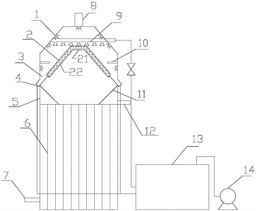
[0067] Such as Figure 1 ~ Figure 3 Shown, a kind of defoaming device comprises electrolyzer 5, and electrolyzer 5 is conventional electrolyzer, and electrolyzer built-in electrode plate 6, the bottom of electrolyzer connects water inlet pipe 7, and top connects outlet pipe 12.

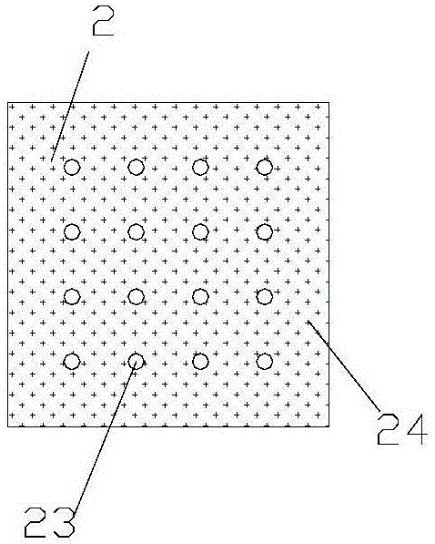
[0068] A defoaming baffle 2 is turned upside down above the electrolytic cell. The defoaming baffle is turned upside down above the electrolytic cell in the shape of a truncated cone, and is composed of a top plate 21 and a side plate 22. The top plate is a circular plate, and the side plates surround the top plate and connect with the top plate. The angle between the junction of the side plate and the top plate is an obtuse angle, preferably 120°-135°, and the vertical height between the top plate and the bottom edge of the side plate is 1 / 6-1 / 4 of the height L of the electrolytic cell.

[0069] The schematic diagram of the defoaming baffle is as follows: image 3 As shown, a number of through holes...


PUM


Abstract

The invention discloses a defoaming device and method for an electrochemical wastewater treatment system. The defoaming device comprises an electrolytic tank, wherein the electrolytic tank is connected with a water inlet pipe and a water outlet pipe; the defoaming device further comprises a defoaming baffle plate inverted above the electrolytic tank, a gas collecting cover arranged above the defoaming baffle plate in a covering manner, a plurality of spray nozzles distributed on an inner wall of the gas collecting cover, and a slag discharging opening which is connected with a bottom edge of the defoaming baffle plate and extends out of the electrolytic tank; a plurality of through holes are formed in the defoaming baffle plate; a plurality of barbs are arranged on one surface, facing the electrolytic tank, of the defoaming baffle plate; the top of the gas collecting cover is connected with an exhaust pipe; the spray nozzles are connected with a high pressure water pump through a pipeline; the slag discharging opening is connected with a foam collecting pool through the pipeline. The defoaming device and method provided by the invention convert part of foam into liquid by utilizing diversion and interception effects of the baffle plate; foam overflowing from the baffle plate is broken by water drops sprayed by high pressure nozzles; the foam and defoamed liquid return to the electrolytic tank along with water flow; a defoaming agent can be added to the electrolytic tank for treatment.

Description

technical field [0001] The invention relates to waste water treatment equipment, in particular to a defoaming device and method for a waste water electrochemical treatment system. Background technique [0002] The electrochemical oxidation process is widely used in the field of wastewater treatment, and has a good treatment effect on refractory chemical wastewater. However, chemical wastewater usually contains a certain amount of surfactants, which will generate a large amount of foam during the electrolysis process, which will lead to deterioration of the working environment, foam overflow and even short circuit of the plates. [0003] Traditional defoamers include emulsified silicone oil, high-carbon alcohol fatty acid ester complex, polyoxyethylene polyoxypropylene pentaerythritol ether, etc., most of which are high-molecular organic substances, which will introduce new pollutants into wastewater and are not easy to remove, especially When the electrochemical oxidation p...

Claims


Application Information

Patent Timeline
Patent Type & Authority Applications(China)
IPC IPC(8): C02F1/20B01D19/02
CPCB01D19/02C02F1/20Y02E60/36
Inventor 沈东升张诗颖冯华军张海洋田志国
Owner SUZHOU INDAL TECH RES INST OF ZHEJIANG UNIV
Why Eureka
Try Eureka