Large bottom water sandstone oil reservoir development physical simulation experiment device and working method thereof

A sandstone reservoir, physical simulation technology, applied in the direction of production fluid, earthwork drilling, measurement, etc., can solve the problems of limited reuse times, difficulty in forming oil and water layers, and no thickness dimension

Active Publication Date: 2017-02-22
CHINA UNIV OF PETROLEUM (EAST CHINA)
View PDF11 Cites 24 Cited by
  • Summary
  • Abstract
  • Description
  • Claims
  • Application Information

AI Technical Summary

Problems solved by technology

In recent years, there have been many studies on the development physical models and simulation methods of sandstone reservoirs with large bottom water, but there are the following deficiencies: (1) Most of them are based on two-dimensional visualization panels, and the development process of bottom water reservoirs cannot be studied from a three-dimensional scale; ( 2) It is not possible to study the lateral displacement under the presence of bottom water energy at the same time, and most models can only study bottom water flooding or lateral displacement; (3) When the model has a certain pressure, some models have saturation (4) Most of the models do not consider the situation of the oil-water layer, and most of them focus on fully saturated oil, so it is difficult to form a good oil-water layer; (5) Currently, the models developed in the market Most of the models are covered with cemented sand resin, the number of reuses is limited, and materials are wasted
But what adopt is cemented fixed model, and can only simulate bottom water drive, the development situation of horizontal well or vertical well, have not considered the situation of model geologic

Method used


Image

  • Large bottom water sandstone oil reservoir development physical simulation experiment device and working method thereof
  • Large bottom water sandstone oil reservoir development physical simulation experiment device and working method thereof
  • Large bottom water sandstone oil reservoir development physical simulation experiment device and working method thereof

Examples


Embodiment 1

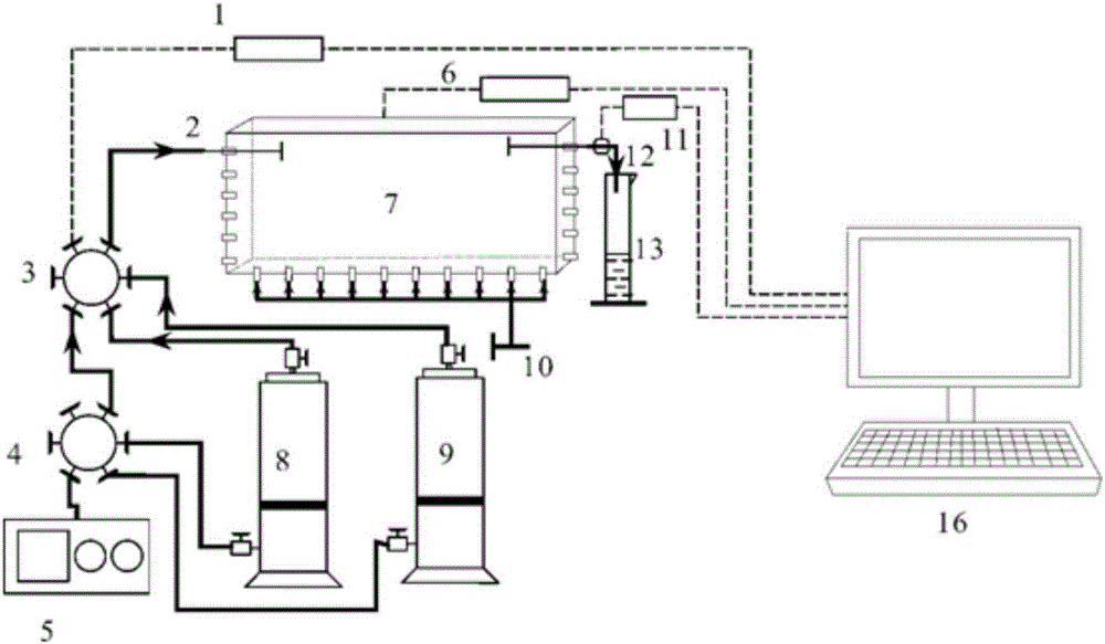
[0050] When this physical model is used for bottom water energy extraction experiments, the experimental steps are as follows:

[0051] Such as figure 2 As shown, in this embodiment, the bottom water injection hole of the body is sequentially connected to the on-off valve 10 , the water storage tank 14 and the gas cylinder 15 through the pipe body.

[0052] The main body of the model 7 uses sand to fill the oil-water layer. The specific method: screen sand with a certain mesh number to wash it with water to remove dust; place the model vertically, and calculate the thickness of the water layer and oil layer according to the thickness ratio of the oil-water layer; Add water repeatedly to the thickness of the water layer, and shake the model during the process of adding sand and water; calculate the pore volume of the water layer; according to the actual formation bound water saturation and water layer porosity as parameters, dry sand is mixed with a certain amount of water and...

Embodiment 2

[0058] When this physical model is used for waterflooding experiments in closed bottom water reservoirs, the experimental steps are as follows:

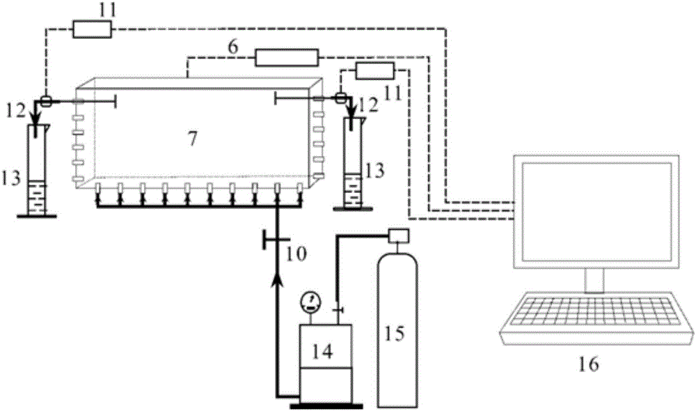
[0059] Such as image 3 As shown, in this embodiment, the natural energy in Embodiment 1 is exploited first until the water content reaches a certain degree, then the bottom water energy switch valve 10 is closed, the left production well is connected to the injection system, and the pressure sensor 1 is monitored at the same time The resulting injection pressure.

[0060] The production well on the right is connected to the pressure control device 11 through the constant pressure control system, that is, the development well 12, to control the production fluid velocity and monitor the wellhead pressure at the same time.

[0061] The production liquid enters the metering device 13 after passing through the constant pressure control system, and accurately measures the liquid production volume.

[0062] The saturation monitoring syst...

Embodiment 3

[0065] When this physical model is used for the unbalanced waterflooding experiment of externally connected bottom water reservoirs, the experimental steps are as follows:

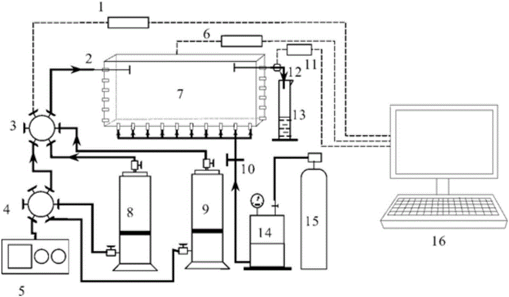
[0066] Such as figure 1 As shown, in this embodiment, the natural energy in Embodiment 1 is exploited first until the water content reaches a certain temperature, and then the injection system is connected to carry out water injection exploitation.

[0067] Calculate the injection-production ratio according to the actual reservoir, control the injection volume and production volume to reach the actual injection-production ratio, and pay attention to the sufficient liquid volume in the water storage tank 14 container in the bottom water system.

[0068] The production well on the right is connected to the pressure control device 11 through the constant pressure control system, that is, the development well 12, to control the production fluid velocity and monitor the wellhead pressure at the same time.

[0...


PUM


Abstract

The invention relates to the field of oil-gas field development, in particular to a large bottom water sandstone oil reservoir development physical simulation experiment device and a working method thereof. A model body is used for constructing an oil layer and a water layer, a bottom water system is used for simulating bottom water energy, the model body is connected with a resistivity meter, and the resistivity meter is connected with a data processing system; an injection system is connected with the model body and used for injecting water or chemical agents for well stimulation into the model body; a mining system is connected with the model body and used for controlling the mining pressure and speed; the data processing system is further connected with the injection system and the mining system separately, monitors changes of a pressure field and a saturation field in real time and controls the mining system. According to the large bottom water sandstone oil reservoir development physical simulation experiment device and the working method thereof, oil and water distribution and pressure distribution of a large bottom water sandstone oil reservoir in the natural energy mining process, the water injection mining process and the well stimulation mining process can be simulated, and a reliable physical simulation model and method are provided for study of the seepage law and the well stimulation effect of the large bottom water sandstone oil reservoir.

Description

technical field [0001] The invention relates to the field of oil and gas field development, in particular to a physical simulation experiment device for the development of large bottom water sandstone reservoirs and a working method thereof. [0002] technical background [0003] Bottom-water sandstone reservoirs are relatively common types of reservoirs, and bottom-water coning or ridges are prone to occur after production, resulting in high water cut in a short period of time, low producing degree of reservoir reserves, and poor development effect. In order to study the remaining oil distribution and stimulation measures in bottom water reservoirs, indoor physical simulation experiments are essential, which play an important role in determining the optimal injection-production mode, the relative position of control and displacement agent injection, and the injection amount of control and displacement agent. In recent years, there have been many studies on the development ph...

Claims


Application Information

Patent Timeline
IPC IPC(8): E21B43/20E21B43/22E21B49/00E21B47/00E21B47/06E21B47/002
CPCE21B43/16E21B43/20E21B47/00E21B47/002E21B47/06E21B49/00
Inventor 戴彩丽方吉超李亮由庆温全义王建海刘广燕赵明伟张雁王欢
Owner CHINA UNIV OF PETROLEUM (EAST CHINA)
Why Eureka
Try Eureka