Silicon carbide semiconductor device
A semiconductor and silicon carbide technology, which is applied in the field of silicon carbide semiconductor devices, can solve the problems of MOSFET gate resistance increase, delay, and polysilicon conductivity is not high enough, and achieve the effect of suppressing the rise of potential and suppressing breakdown
- Summary
- Abstract
- Description
- Claims
- Application Information
AI Technical Summary
Problems solved by technology
Method used
Image
Examples
Embodiment approach
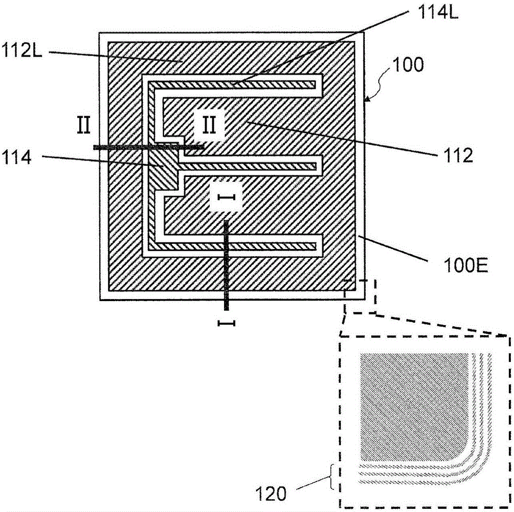
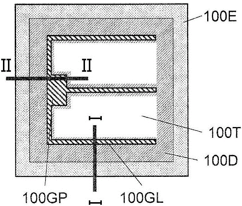
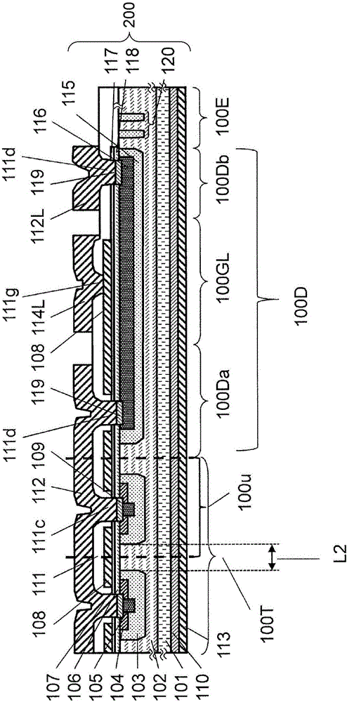
[0069] Referring to Figure 1, figure 2 as well as image 3 Embodiments of the silicon carbide device of this embodiment will be described. Figure 1A It is a schematic plan view of silicon carbide semiconductor device 100 (hereinafter, referred to as SiC-MOSFET 100 ) according to the present embodiment viewed from the principal surface side of the semiconductor substrate. figure 2 yes Figure 1A A schematic cross-sectional view at line I-I is shown, image 3 yes Figure 1A Schematic cross-sectional view at line II-II shown.
[0070]
[0071] SiC-MOSFET 100 of the present embodiment includes stacked structure 200 . The stacked structure 200 includes an n+ type SiC substrate (semiconductor substrate) 101, a drift layer (first silicon carbide semiconductor layer) 102 located on the main surface of the SiC semiconductor substrate 101, and a drain electrode (the first silicon carbide semiconductor layer) located on the back surface of the SiC semiconductor substrate 101. One...
Deformed example 1
[0134] refer to Figure 9 Modification 1 of the semiconductor device of this embodiment will be described.
[0135] As described in the above embodiment, since a large current such as a displacement current or an avalanche current flows through the source wiring of the diode region 100Db, it is preferable to make the width of the source wiring as wide as possible. However, when there is only the diode region 100Db under the upper source wiring, the area other than the transistors in the entire chip increases, the average current amount of the chip area is low, and the on-resistance increases. That is, the area efficiency is poor. Modification 1 is characterized in that a transistor cell is arranged also under the source wiring. Accordingly, it is possible to reduce the decrease in the average current amount of the chip area when the source wiring width is widened.
[0136] Figure 9 A schematic cross-sectional view of Modification 1 of the present embodiment is shown. SiC...
Deformed example 2
[0143] refer to Figure 10 Modification 2 of the semiconductor device of this embodiment will be described.
[0144] Since there is a region thinner than the upper electrode in the upper source wiring 112L, it is preferable to prevent a large current from flowing as much as possible. In particular, in the case of avalanche breakdown, a current equal to the rated current may be discharged from the corner to the outside through the upper source wiring. In SiC-MOSFET 900 according to Modification 2 of the present embodiment, multilayer structure 200 has a substantially quadrilateral shape when viewed from a direction perpendicular to the principal surface of SiC semiconductor substrate 101 . Among the four corners 200a, 200b, 200c, and 200d of the quadrilateral, the withstand voltage of the terminal region 100E in the corners 200a, 200b located closer to the gate pad 114 is at least higher than that in the other two corners 200c, 200d. The withstand voltage of the terminal regi...
PUM
 Abstract
Description
Claims
Application Information
 - R&D
- Intellectual Property
- Life Sciences
- Materials
- Tech Scout
- Unparalleled Data Quality
- Higher Quality Content
- 60% Fewer Hallucinations
Browse by: Latest US Patents, China's latest patents, Technical Efficacy Thesaurus, Application Domain, Technology Topic, Popular Technical Reports.
© 2025 PatSnap. All rights reserved.Legal|Privacy policy|Modern Slavery Act Transparency Statement|Sitemap|About US| Contact US: help@patsnap.com


