Supercharge Your Innovation With Domain-Expert AI Agents!

Surface modification method and device for modifying surface of inner wall of hole by utilizing laser overlaying welding

A surface modification, laser beam technology, used in laser welding equipment, welding equipment, metal processing equipment and other directions, can solve the problem of limited welding torch size and other issues

Active Publication Date: 2017-03-01
SHANGHAI JIAO TONG UNIV
View PDF19 Cites 7 Cited by
  • Summary
  • Abstract
  • Description
  • Claims
  • Application Information

AI Technical Summary

Problems solved by technology

[0005] Therefore, it can be seen that although there are some technical improvements in the surfacing welding of the inner wall of the pore, there are still limitations due to the technology or process itself. Limited by the size of the welding torch, the inner wall of a hole with a smaller inner diameter cannot be surfacing in this way

Method used


Image

  • Surface modification method and device for modifying surface of inner wall of hole by utilizing laser overlaying welding
  • Surface modification method and device for modifying surface of inner wall of hole by utilizing laser overlaying welding
  • Surface modification method and device for modifying surface of inner wall of hole by utilizing laser overlaying welding

Examples


application example 1

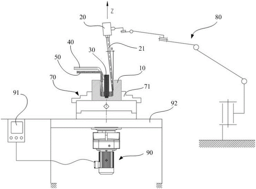
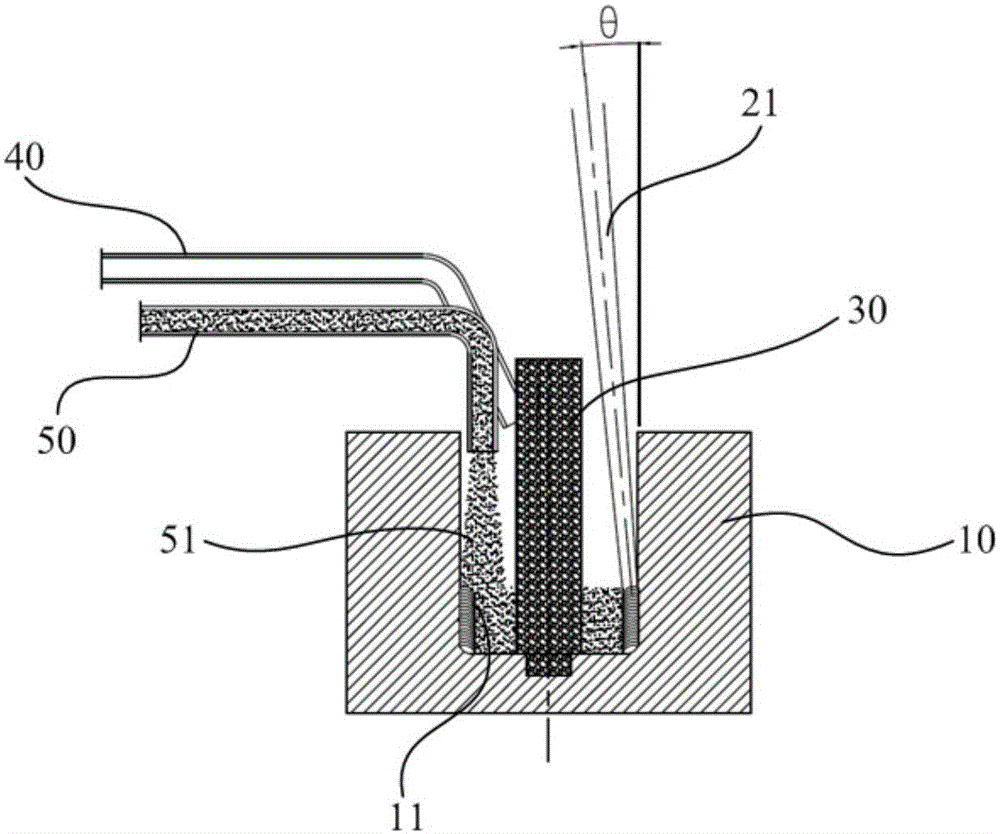
[0082] The blind hole in the workpiece 10 has a diameter of 35mm and a depth of 420mm, and the step of surface modification of the inner wall of the blind hole includes:

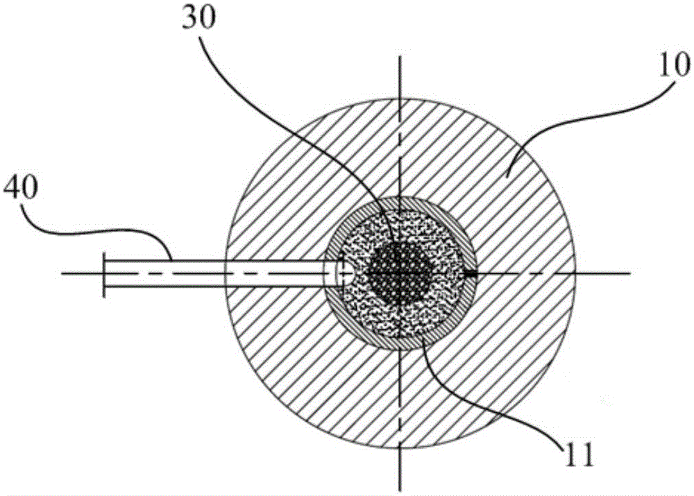
[0083] A counterbore is provided on the bottom surface 10b of the blind hole of the workpiece 10 for fixing the spacer 30;

[0084] The workpiece 10 is clamped on the three-jaw chuck 71, and then the isolation part 30 is installed on the counterbore, and the isolation part 30 is a cylinder made of copper with a diameter of 15 mm;

[0085] Adjust the orientation of the laser 20 so that the laser beam 21 can be obliquely irradiated on the surface of the inner wall 10a of the blind hole through the opening of the blind hole of the workpiece 10, and the inclination angle θ is 8°; and adjust the initial position of the laser 20 so that the laser beam 21 The initial position of the light spot on the surface of the inner wall 10a is at the edge of the bottom surface 10b; wherein, the beam diameter of the laser beam...

application example 2

[0090] The blind hole in the workpiece 10 has a diameter of 20mm and a depth of 180mm, and the step of surface modification of the inner wall of the blind hole includes:

[0091] A counterbore is provided on the bottom surface 10b of the blind hole of the workpiece 10 for fixing the spacer 30;

[0092] The workpiece 10 is clamped on the three-jaw chuck 71, and then the isolation part 30 is installed on the counterbore. The isolation part 30 is a cylinder made of alumina ceramics with a diameter of 7 mm;

[0093] Adjust the orientation of the laser 20 so that the laser beam 21 can be obliquely irradiated on the surface of the inner wall 10a of the blind hole through the opening of the blind hole of the workpiece 10, and the inclination angle θ is 3°; and adjust the initial position of the laser 20 so that the laser beam 21 The initial position of the light spot on the surface of the inner wall 10a is at the edge of the bottom surface 10b; wherein, the beam diameter of the laser...


PUM

PropertyMeasurementUnit
Diameteraaaaaaaaaa
Diameteraaaaaaaaaa

Abstract

The invention discloses a surface modification method used for the surface of an inner wall of a hole of a workpiece. The method comprises following steps: utilizing laser beams to overlay surfacing material by melting and further comprises the steps of keeping an opening of the hole facing upward; using laser beams to irradiate the surface through the opening such that movement that light spots of laser beams perform on the surface relative to the hole comprises first movement along the axial direction of the hole and second movement surrounding the axial direction, thereby enabling the light spots to scan all over the surface. Correspondingly, the invention provides a surface modification device. By applying the surface modification method to the workpiece placed on the surface, an overlaying welding layer grows out of the surface of the inner wall of the hole of the workpiece. Compared with the prior art, the surface modification method used for the surface of the inner wall of the hole of the workpiece has following beneficial effects: the method is easy in operation, convenient in preparation and has efficient production efficiency, and particularly is capable of performing laser overlaying welding on the surface of the inner wall of a deep hole with a small hole diameter.

Description

technical field [0001] The invention relates to the surface modification technology of materials, in particular to a surface modification method and device for modifying the surface of the inner wall of a hole by laser surfacing welding. Background technique [0002] Overlay welding is a process method of welding wear-resistant, corrosion-resistant and other special performance metal layers on the surface of metal materials or parts. It can not only repair metal parts and products with unqualified dimensions, or manufacture bimetallic parts, but also The surface performance of metal parts can be further improved by rational selection of surfacing materials. [0003] Among various surfacing technologies such as arc powder surfacing, plasma arc surfacing, etc., laser surfacing uses a high-energy-density laser beam as a heat source to weld surfacing material powder on the surface of metal materials or parts, which has advantages : 1. The heat input can be accurately controlled...

Claims


Application Information

Patent Timeline
IPC IPC(8): B23K26/342B23K26/08B23K26/14B23K26/70
CPCB23K26/083B23K26/0892B23K26/14
Inventor 姚成武黄坚冯凯陈源李铸国
Owner SHANGHAI JIAO TONG UNIV
Features
  • R&D
  • Intellectual Property
  • Life Sciences
  • Materials
  • Tech Scout
  • Unparalleled Data Quality
  • Higher Quality Content
  • 60% Fewer Hallucinations
Learn More