Micro-device for removing cell cryoprotective agent on basis of multistage dialysis method

A cryoprotectant and cell removal technology, which is applied in the field of medical devices, can solve the problems of low cell recovery rate, low removal efficiency, and large cell damage, and achieve high cell survival rate and recovery rate.

Active Publication Date: 2017-03-08
UNIV OF SCI & TECH OF CHINA
View PDF4 Cites 5 Cited by
  • Summary
  • Abstract
  • Description
  • Claims
  • Application Information

AI Technical Summary

Problems solved by technology

At present, although microfluidic technology has been used for the removal of cryoprotectants, the low removal efficiency, large cell damage, low...

Method used


Image

  • Micro-device for removing cell cryoprotective agent on basis of multistage dialysis method
  • Micro-device for removing cell cryoprotective agent on basis of multistage dialysis method
  • Micro-device for removing cell cryoprotective agent on basis of multistage dialysis method

Examples


Embodiment 1

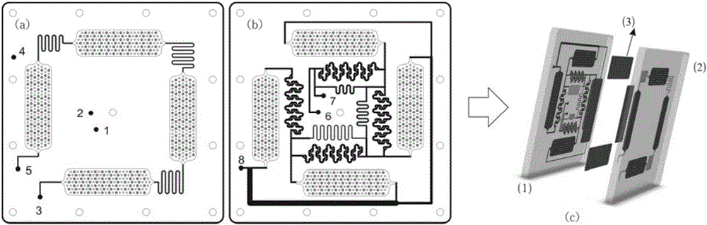
[0051] have figure 1 A conceptual diagram of the upper and lower board chips and a structural schematic diagram of the device for a micro-device that removes the cryoprotectant of the cells shown in the structure, including:

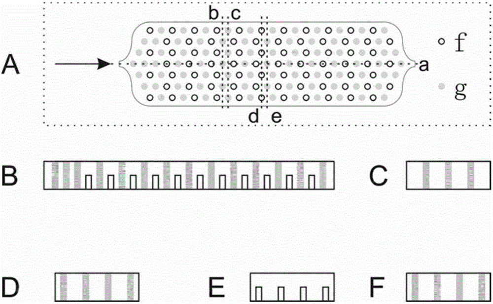
[0052] The upper and lower chips of the microdevice for removing the cryoprotectant from cells are square upper and lower chips with a length, width and height of 12.8cm×12.8cm×0.6cm; the material of the upper and lower chips is organic glass (PMMA). The first channel on the lower surface of the upper chip includes a cell suspension channel and 4 dialysis units, wherein the dialysis units are embedded in a staggered array of miniature cylinders (diameters are 1mm, the height of the high column is 0.5mm, and the height of the low column is 0.25mm). ) rectangular groove (length, width and height are 5.0cm×1.5cm×0.5mm), the high and low columns are distributed in a wavy manner perpendicular to the fluid flow direction, a group of wavy high columns, a group ...

Embodiment 2

[0057] A micro-device for clearing cell cryoprotectants provided in Example 1 is used to remove glycerin, and the specific process is:

[0058] The compound glycerin solution with a mass volume ratio of 57% is dropped into the red blood cell solution drop by drop, and mixed evenly to obtain a red blood cell suspension containing 10-40% glycerin, and the volume ratio thereof is 6±5%-24±5%;

[0059] The cell suspension is passed into the first channel inlet 3 of the working platform for continuously removing the cryoprotectant in the cell suspension provided in Example 1, and the cell suspension flows into the dialysis successively along the first channel for execution Area;

[0060] Deionized water is passed into from the horizontal hypotonic channel inlet 1 of the first channel, and simultaneously the Nacl solution (mass / volume ratio) with a concentration of 20% is passed from the horizontal hypertonic channel inlet 2 of the first channel Filling, deionized water and Nacl sol...


PUM

PropertyMeasurementUnit
Membrane pore sizeaaaaaaaaaa

Abstract

The invention provides a micro-device for removing a cell cryoprotective agent on the basis of a multistage dialysis method. The micro-device comprises an upper chip with a first channel, a lower chip with a second channel, and a porous membrane, wherein the porous membrane is arranged between the dialysis units of the upper chip and the dialysis units of the lower chip; the first channel comprises a cell suspension channel and four dialysis units; the second channel comprises a dialysis liquid generating area, four dialysis units and a dialysis liquid collecting area; the dialysis units of the first channel, the dialysis units of the second channel and the porous membrane form a dialysis executing area. When the micro-device operates, the dialysis liquid generating area of the second channel generates gradient-concentration and variable-flow dialysis liquid, and the dialysis liquid flows into the dialysis executing area to dialyze the cell suspension in the dialysis units of the first channel. The micro-device has the advantages that the micro-device can effectively remove the cryoprotective agent in the cell suspension, reduce cell mechanical damage and osmotic pressure damage, and increase cell survival rate and recycling rate.

Description

technical field [0001] The invention relates to the technical field of medical devices, in particular to a micro-device for removing cryoprotectants from cells based on multistage dialysis, which can be used to remove cryoprotectants from cells, and can also be used for red blood cell drug loading or cell labeling. Background technique [0002] Cryopreservation is an important technique for the preservation of precious cells in fields such as reproductive medicine, tissue regeneration, and cell therapy. Cryoprotectants can protect cells from low temperature damage during cryopreservation, but because of their negative effects, they need to be removed before use. Most of the cell samples required in some clinical treatments (such as: stem cell / immune cell therapy, etc.) and basic research (such as cell-on-a-chip laboratory, tissue engineering, etc.) If the cryoprotectant is not removed, it will affect the clinical treatment effect and the results of basic research. Therefor...

Claims


Application Information

Patent Timeline
IPC IPC(8): C12M1/12C12N5/078
CPCC12N5/00C12N5/0641
Inventor 丁卫平邹丽丽康玉峰刘婧刘娟娟邱本胜
Owner UNIV OF SCI & TECH OF CHINA
Why Eureka
Try Eureka