Low noise block circuit and low noise block

A high-frequency head and circuit technology, applied in the field of frequency reduction, can solve the problems of increasing product material costs and labor assembly costs, inter-stage loss and signal interference, and existing hidden dangers, saving material costs and labor costs, and weakening mutual Interference, improve the effect of output utilization

Active Publication Date: 2017-03-08
重庆幂天通讯设备制造有限责任公司
View PDF6 Cites 3 Cited by
  • Summary
  • Abstract
  • Description
  • Claims
  • Application Information

AI Technical Summary

Problems solved by technology

[0004] The disadvantages of the above two design structures are: 1) After the signal is processed by the first-stage intermediate frequency amplifier, it needs to be balanced by the intermediate frequency power divider, and then transmitted to the two sets of switching selector switches. During the signal transmission process, there are inter-stage losses and signal Interference; 2) After the signal is divided by the intermediate frequency, the signal needs to be output by connecting the PIN pin branch, that is, there are two PCBs combined to connect, this structure increases the product material cost and labor assembly cost; 3) The product has been processed many times, relatively external factors The stability caused by it is affected, and there are bad hidden dangers

Method used


Image

  • Low noise block circuit and low noise block
  • Low noise block circuit and low noise block
  • Low noise block circuit and low noise block

Examples


Embodiment 1

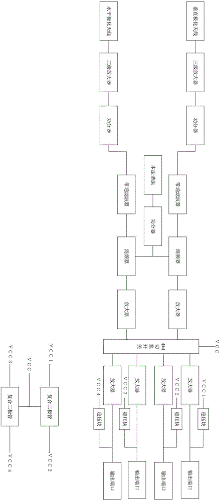
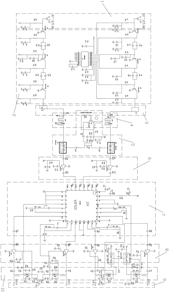
[0034] Such as Figure 1-5 As shown, a tuner circuit includes a radio frequency receiving module 1, a radio frequency amplifying module 2, a radio frequency power dividing module 3, a high frequency filtering module 4, a single local oscillator mixing module 5, and a first-stage intermediate frequency amplifying module 6 connected in sequence , switch 5, secondary intermediate frequency amplification module 8 and several output ports 9.

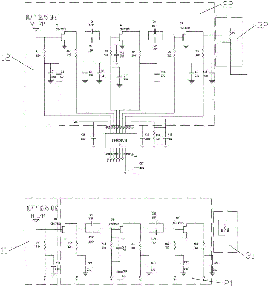
[0035] The radio frequency receiving module 1 includes a horizontally polarized antenna 11 and a vertically polarized antenna 12, which are respectively used to receive ku-band radio frequency signals in the spatial horizontal and vertical directions, and the ku-band frequency is 10.7~12.75GHz;

[0036] The radio frequency amplification module 2 includes a three-stage amplifier 21 composed of a first amplifier, a second amplifier and a third amplifier for amplifying horizontally polarized signals, and a fourth amplifier and a fifth amplifier ...

Embodiment 2

[0061] Such as Figure 9 and 10 , a tuner, comprising a waveguide 202, a waveguide port 201 connected to both ends of the waveguide 202 and a carrier board 205, the carrier board 205 is provided with a PCB 203, and the PCB 203 is provided with an implementation For the tuner circuit described in Example 1, several wiring holes 204 are provided on the carrier board 205 .

[0062] In a traditional tuner, PCBs are generally provided on both sides (front and back) of the carrier board 205 for the wiring of the tuner circuit. After using the optimized circuit in Embodiment 1, only one PCB is needed 203 (the back of the carrier board 205) can complete the wiring of the entire tuner circuit, which greatly saves material costs and labor costs, and the output intermediate frequency signal is more stable without noise interference.


PUM


Abstract

The invention discloses a low noise block circuit and a low noise block. The low noise block circuit comprises a radio-frequency receiving module, a radio-frequency amplifying module, a radio-frequency power dividing module, a high-frequency filtering module, a single local oscillation frequency mixing module, a primary medium-frequency amplifying module, a shift switch, a secondary medium-frequency amplifying module and a plurality of output ports which are connected in sequence, wherein a low-frequency output port of the radio-frequency power-dividing module is unoccupied; and a high-frequency output port of the radio-frequency power-dividing module is connected with the high-frequency filtering module. A medium-frequency power dividing module is removed from the low noise block circuit, so that the wiring of a PCB (Printed Circuit Board) circuit is optimized; output of four paths of medium-frequency signals is realized; loss and mutual interference of the signals during transmission are lowered; the aim of wiring on a single panel of the low noise block is fulfilled; product performance is improved; the product Q value is increased; and the product material cost and manual operation cost are lowered.

Description

technical field [0001] The invention relates to the field of frequency reduction, in particular to a tuner circuit and a tuner. Background technique [0002] The working principle of satellite dish receiving satellite TV is to use the satellite dish to collect weak satellite signal and reflect the satellite signal to the LNB installed at the focal point of the dish antenna. Then, the tuner amplifies the concentrated signal and reduces the RF frequency to an intermediate frequency of about 1GHz to 2GHz, and then transmits it to the indoor receiver or digital output port group through the cable, and the receiver selects the channel to be watched in the signal , After being amplified and demodulated and restored to image and sound signals, they are input into the TV to play the program. [0003] According to the market area and customer needs, the LNB also uses a single local oscillator, dual polarization and multiple output products, such as circular polarization (ie Circular...

Claims


Application Information

Patent Timeline
Patent Type & Authority Applications(China)
IPC IPC(8): H04N7/20H04N5/50
CPCH04N5/50H04N7/20
Inventor 袁萍洪加亮钟艳邓诒谨
Owner 重庆幂天通讯设备制造有限责任公司
Why Eureka
Try Eureka