Radioactive lumen stent

A radioactive and radionuclide technology, which is applied in the field of radioactive lumen stents, can solve the problems of reducing the flexibility of the stent, occupying the cavity space for implantation, and reducing the flexibility of the stent, and achieves easy preparation or realization and maintenance of drainage effect. , to maintain the effect of treatment

Pending Publication Date: 2017-03-22
窦春青 +1
View PDF8 Cites 2 Cited by
  • Summary
  • Abstract
  • Description
  • Claims
  • Application Information

AI Technical Summary

Problems solved by technology

[0014] First, due to the thin wire of the mesh stent and the thin wall of the solid stent, although the size of the radioactive particles is small (0.8mm in outer diameter and 4.5mm in length), compared with the wire of the mesh stent and the wall of the solid stent, the radioactive particles The outer diameter is still larger, so fix or fill 125 The operation of I particles is relatively difficult;
[0015] Second, the movement of the lumen or substances in the lumen may easily cause the radioactive particles to fall off and migrate, which may cause damage to normal lumen tissue or other tissues;
[0016] Third, for lumens with larger inner diameters such as the esophagus, 125 I particles will not occupy more lumen space, but for lumens with small inner diameters such as biliary tract, 125 The introduction of I particles increases the overall volume of the stent, and the implantation cavity occupies a large cavity space, which affects normal physiological activities;
[0017] Fourth, the important feature of the stent is its flexibility, but the introduction of radioactive particles reduces the flexibility of the stent, making it difficult to place the implant or implant the lumen, and will change the natural position of the lumen in the body. Squeeze surrounding tissues or organs, causing adverse effects
[0026] First, the thickness of the tube wall outside the drainage cavity of the tube stent is generally no more than a few millimeters, and some are even only about 0.5-1mm. However, the outer diameter of radioactive particles is relatively large, which makes the realization of this design more difficult, or after the design is realized, the thickness of the stent body near the particles becomes very thin, which may be easily damaged;
[0027] Second, the shell of the particles is a hard titanium tube. After being inserted into the tube wall, the flexibility of the stent will be reduced. The deformation of the stent, rather than the deformation of the stent along with the pipeline, will change the natural shape or position of the lumen tissue in the body, squeeze the surrounding tissues or organs, and cause adverse effects;
[0028] Third, radioactive particles are point sources. To form a regional dose distribution, it is usually necessary to implant multiple particles, which will amplify the first and second disadvantages above.

Method used


Image

  • Radioactive lumen stent
  • Radioactive lumen stent
  • Radioactive lumen stent

Examples


Embodiment 1

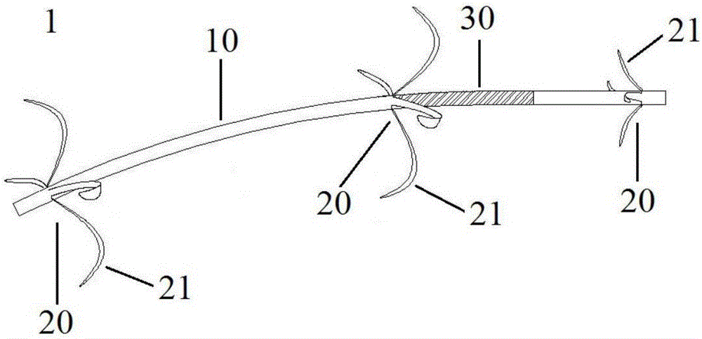
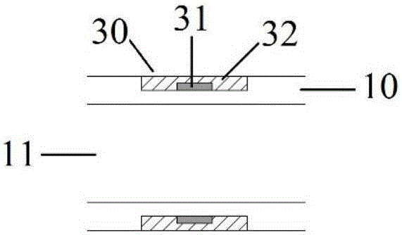
[0066] Such as Figure 1-2 Shown: a radioactive luminal stent 1, including a tube body 10, branch-shaped support wings 20, and a radiation core 31 sealed in the tube body 10, the radiation core 31 being silver foil loaded with radionuclides. The inner wall of the tube body 10 is smooth, and the outer wall of the tube body 10 is smooth except for the branch-shaped supporting wings 20 and grooves.

[0067] There is an annular groove on the outside of the pipe body 10, and the middle part of the groove is wrapped with 125 The silver foil of I, the silver foil wraps the casing and fills the whole groove. The surface of the casing after wrapping the groove is smooth and equal to the outer surface of the pipe body 10 to form a smooth surface.

[0068] The two ends of the pipe body 10 and near the loaded 125 There are branch-shaped support flanks 20 on one side of the near-end of the radiation region produced by the silver foil of I, and each branch-shaped support flank 20 structur...

Embodiment 2

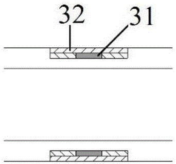
[0075] The implementation mode of embodiment two is the same as that of embodiment one, and the differences are as follows: image 3 As shown: there is an annular groove on the outside of the tube body 10, the middle part of the groove is wrapped with silver foil carrying radionuclides, the other part of the groove is wrapped with a film of equal thickness to the silver foil, and the silver foil and the film are wrapped outside the casing and fill the entire cavity. groove.

Embodiment 3

[0077] The implementation mode of the third embodiment is the same as that of the first embodiment, the differences are as follows Figure 4 As shown: both ends of the tube body 10 and the proximal end of the radioactive region 30 produced by the silver foil loaded with radionuclides have branch-shaped support wings.


PUM


Abstract

The invention relates to the technical field of medical instruments containing radioactive substances and discloses a radioactive lumen stent which comprises a tube body, a branch-shaped supporting side wing and a sheet-shaped radioactive core sealed in the wall of the tube body and carrying radioactive nuclide. The branch-shaped supporting side wing is used for fixing the stent at a specific position in a tube cavity to prevent displacement; the radioactive core carries the radioactive nuclide and also plays a role as an X-ray marker, and the radioactive nuclide releases radioactive rays to treat tumor during decaying. The radioactive lumen stent is simple in structure and high in flexibility, is maintained smooth on the surface, is convenient for implantation, extraction and replacement with the help of an endoscope and has effects of supporting, draining and treating; due to structure of the radioactive core arranged on the tube body, leakage of the radioactive nuclide can be avoided; the radioactive core is quite thin, thereby having little influence on size of the stent; a sectional radiation designing mode is adopted, so that 360-degree blind-spot-free radiation is realized, size of a radioactive area, type of nuclide, position on the support and activity of the nuclide can be adjusted according to clinical features like position and size of the tumor, and individualized precision treatment is realized.

Description

technical field [0001] The invention belongs to the technical field of medical devices containing radioactive substances, and in particular relates to a radioactive luminal stent, which can be used for treating cholangiocarcinoma and pancreatic cancer, and can also be used for treating other luminal malignant tumors. Background technique [0002] Lumenal organs are important components of the human body, such as esophagus, intestinal tract, trachea, bile duct, blood vessels, etc. Luminal malignancies seriously affect health, and lumen stenosis and obstruction caused by luminal malignancies have always plagued human beings. [0003] Lumen stenosis and obstruction caused by malignant luminal tumors are usually alleviated by implanting stents, which can achieve good results in the short term, but stents themselves are meaningless for tumor treatment, and re-stenosis usually occurs as tumors proliferate, resulting in the need for Insert the stent again. [0004] The treatment o...

Claims


Application Information

Patent Timeline
Patent Type & Authority Applications(China)
IPC IPC(8): A61M36/12
CPCA61N5/1002A61N5/1014A61N2005/1092A61N2005/1085
Inventor 窦春青李忠勇
Owner 窦春青
Why Eureka
Try Eureka