
A Differential Amplifying Circuit with Adaptive Load

A differential amplifier circuit, adaptive load technology, applied in differential amplifiers, DC-coupled DC amplifiers, amplifiers, etc., can solve problems such as increasing circuit complexity, and achieve the effects of improving flatness, improving linearity, and delaying phase distortion

Active Publication Date: 2019-11-15
RDA MICROELECTRONICS SHANGHAICO LTD
View PDF7 Cites 0 Cited by
  • Summary
  • Abstract
  • Description
  • Claims
  • Application Information

AI Technical Summary

Problems solved by technology

However, this solution involves feedback adjustment between multiple amplifying units, and the separate adjustment of frequency compensation and reduction of amplitude distortion increases the complexity of the circuit

Method used


Image

  • A Differential Amplifying Circuit with Adaptive Load
  • A Differential Amplifying Circuit with Adaptive Load
  • A Differential Amplifying Circuit with Adaptive Load

Examples


Embodiment Construction

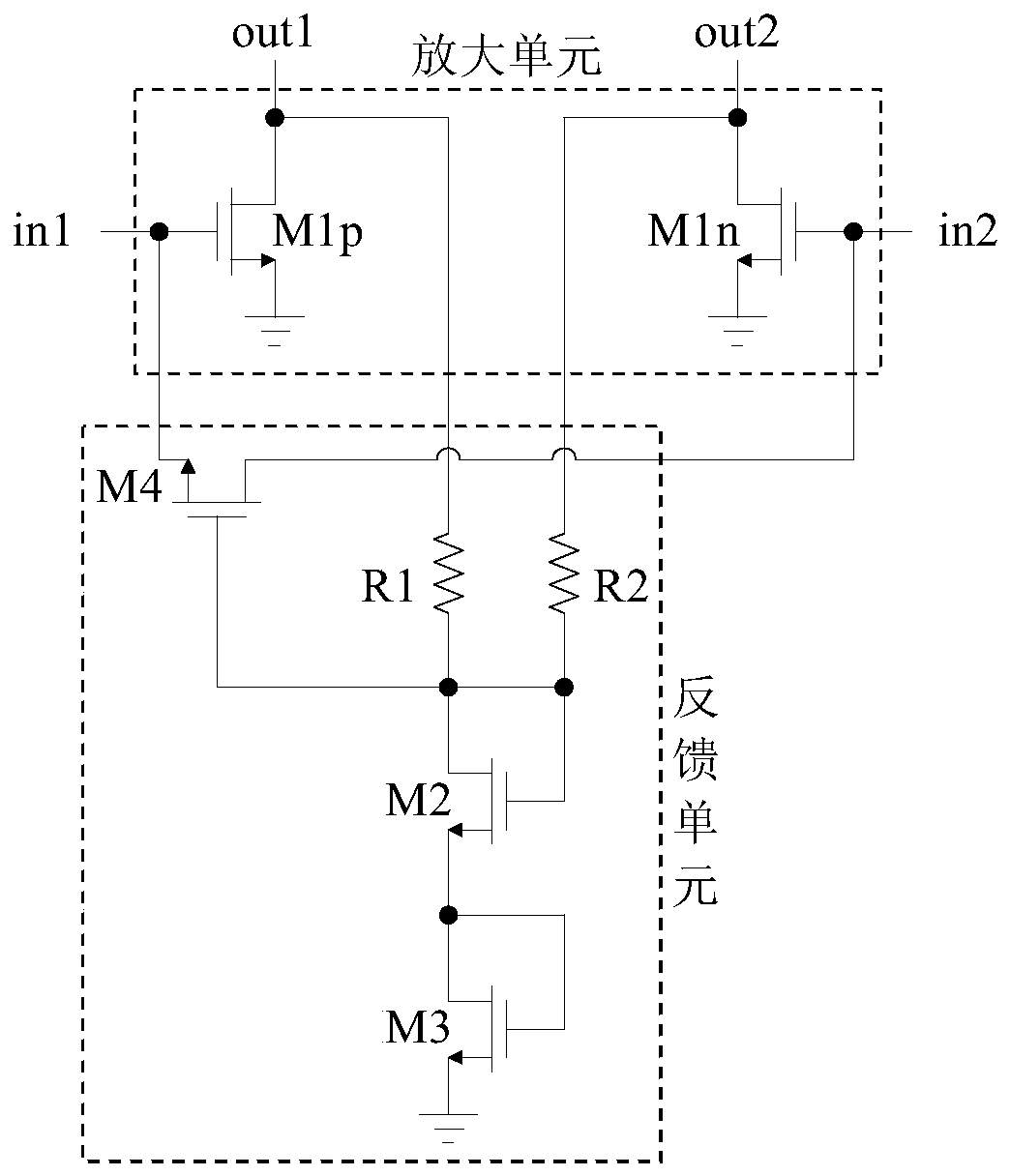
[0023] See figure 2 This is the first embodiment of the adaptive load differential amplifier circuit provided in this application, which includes an amplifier unit and a feedback unit.

[0024] The amplifying unit adopts a pair of transistors M1p and M1n with a differential structure as power amplifying elements, and respectively amplifies a pair of differential input signals and outputs a pair of differential output signals. The gates of the pair of transistors M1p and M1n serve as a pair of differential input terminals in1 and in2, the sources of the pair of transistors M1p and M1n are grounded, and the drains of the pair of transistors M1p and M1n serve as a pair of differential input terminals. Output terminals out1 and out2. The pair of transistors M1p and M1n are, for example, MOS transistors.

[0025] The feedback unit includes transistor two M2, transistor three M3 and transistor four M4. The drain and gate of transistor two M2 are short-circuited, and the gate of transi...


PUM


Abstract

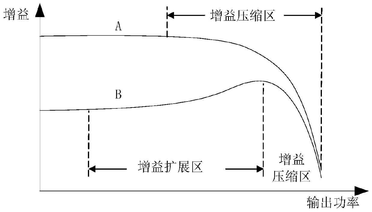
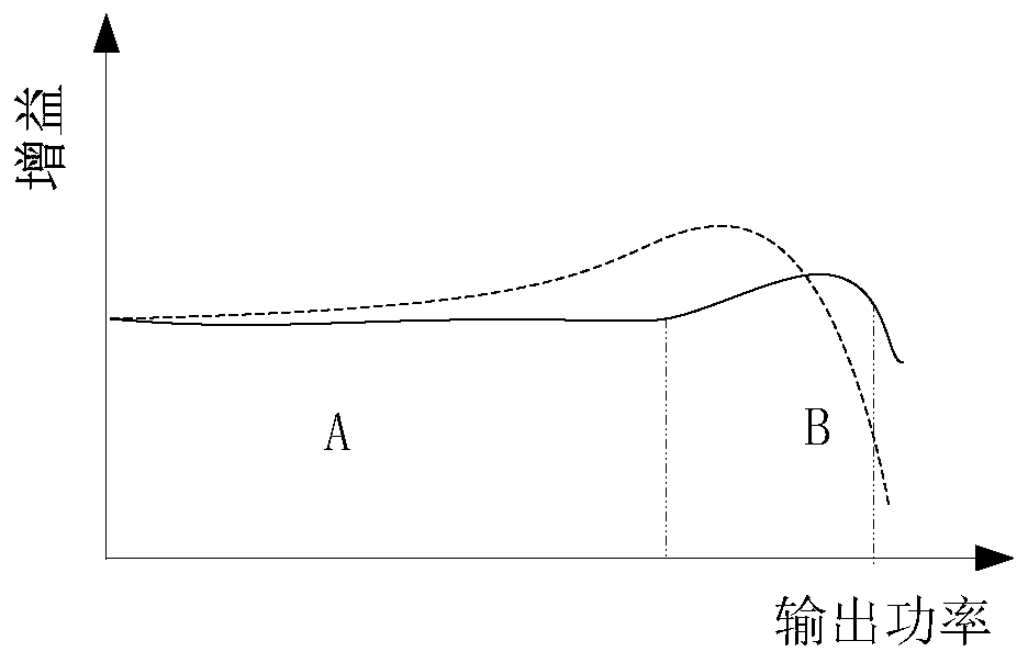
The invention discloses a differential amplification circuit of a self-adaption load. The differential amplification circuit comprises an amplification unit and a feedback unit, and the amplification unit is of a difference structure and is used for amplifying a pair of differential input signals and outputting a pair of differential output signals. The feedback unit comprises at least two diodes and at least one feedback transistor, and the two diodes are cascaded; a first end of a cascaded branch of the diodes is an anode of one diode and is connected with a grid electrode of the feedback transistor; the second end of the cascaded branch of the diodes is a cathode of the other diode and is connected with the ground; the grid electrode of the feedback transistor is connected with a pair of differential output ends or a pair of central nodes of the amplification unit through two resistors, and a drain electrode and a source electrode of the feedback transistor are respectively connected with a pair of differential input ends of the amplification unit. According to the invention, the AM-AM evenness can be improved, phase distortion is delayed, and the linearity is improved.

Description

Technical field [0001] This application relates to a radio frequency signal amplifying circuit, which can be used as a certain stage amplifying unit in a linear power amplifier. Background technique [0002] An RF power amplifier is an electronic amplifier used to convert a lower power radio frequency signal into a higher power. The typical application of the RF power amplifier is to drive the antenna in the transmitter, that is, to amplify the modulated RF signal to the required power value and send it to the antenna for transmission. The design indicators of RF power amplifiers usually include gain, output power, bandwidth, efficiency, linearity, input and output impedance matching, heat generation, etc. [0003] The efficiency of the RF power amplifier refers to its ability to convert the DC power of the power supply into the output power of the RF signal. The power of the power source that is not converted into the output power of the radio frequency signal becomes heat radia...

Claims


Application Information

Patent Timeline
Patent Type & Authority Patents(China)
IPC IPC(8): H03F1/56H03F1/32H03F3/45
CPCH03F1/3211H03F1/56H03F3/45179H03F2200/451H03F2203/45022
Inventor 孙亚楠江亮张海兵贾斌
Owner RDA MICROELECTRONICS SHANGHAICO LTD
Learn More