Light beam intensity, phase distribution and polarization modulation device

A beam intensity and phase distribution technology, applied in the field of optical signal processing, can solve the problems of complex operation, inability to simultaneously modulate its intensity and phase, and high cost, and achieve the effects of simple operation, low device cost, and high conversion efficiency

Inactive Publication Date: 2017-04-19
UNIV OF SHANGHAI FOR SCI & TECH
View PDF1 Cites 7 Cited by
  • Summary
  • Abstract
  • Description
  • Claims
  • Application Information

AI Technical Summary

Problems solved by technology

[0006] The present invention aims at the problem that the existing modulation device of beam intensity, phase and polarization state is complex in operation and expensive, and cannot simultaneously modulate the intensity and phase of a beam of special polarization state, and proposes a beam intensity, phase distribution And the modu

Method used


Image

  • Light beam intensity, phase distribution and polarization modulation device

Examples


Embodiment Construction

[0010] The laser described in the following example system is an example of a fiber laser with an emission wavelength of 800 nm, a pulse width of 100 fs, and a power of 150 mW. The other bands are implemented in the same way as this band.

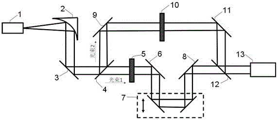
[0011] Such as figure 1 Schematic diagram of the structure of the modulating device for beam intensity, phase distribution and polarization state shown. The femtosecond laser 1 emits laser light, the beam is adjusted to a parallel beam through the parabolic mirror 2, and the beam passes through the mirror 3 and reaches the beam splitter 4 and is divided into two paths: the transmitted beam 1 and the reflected beam 2. The transmitted light beam 1 passes through the first spatial light modulator 5 and then enters the delay device 7 through the reflective mirror 6, and then reaches the beam splitter 12 after passing through the reflective mirror 8; the reflected light beam 2 passes through the reflective mirror 9 and enters the second spatial...


PUM


Abstract

The invention relates to a light beam intensity, phase distribution and polarization modulation device. A femtosecond laser emits laser, and a light beam is adjusted to be a parallel light beam through a paraboloid mirror. The light beam passes through a first reflector, and reaches a beam splitting mirror to be divided into two light beams: the transmitting light beam passes by a first spatial light modulator and then passes by a second reflector to enter a time delay device, and finally passes through a third reflector to reach the beam splitting mirror; and the reflected light beam passes by a fourth reflector and then passes by a second spatial light modulator and a fifth reflector to reach a beam combiner; the combined light beam is outputted to a detection device. The first spatial light modulator, the second spatial light modulator and the detection device are connected with a computer. The spatial light modulators are controlled through a computer optimization algorithm, and achieve the modulation of light beam intensity, phase and polarization at the same time. The device is simple in structure, is low in device cost, and is wide in application range.

Description

technical field [0001] The invention relates to an optical signal processing technology, in particular to a modulation device for beam intensity, phase distribution and polarization state. Background technique [0002] Optical modulation is widely used in the field of optical research. Optical modulation is to superimpose a signal carrying information on the carrier light wave. The device that completes this process is called a modulator. The modulator can make the parameters of the carrier light wave change with the external signal, and these parameters include the amplitude, phase, frequency, polarization, wavelength, etc. of the light wave. The modulated light wave carrying information can obtain the required information after being demodulated by the photodetector system. Optical modulation technology has been widely used in optical communication, ranging, optical information processing, optical storage and display, etc. [0003] A spatial light modulator is a device t...

Claims


Application Information

Patent Timeline
IPC IPC(8): G02B27/10G02B27/28
CPCG02B27/1026G02B27/283
Inventor 彭滟朱亦鸣张竹倩殷晨晖王俊炜庄松林
Owner UNIV OF SHANGHAI FOR SCI & TECH
Why Eureka
Try Eureka