Solid waste pyrogenation and combustion system

A combustion system and solid waste technology, applied in the direction of combustion method, combustion type, combined combustion mitigation, etc., can solve the problems of difficult survival of enterprises, energy waste, and difficult utilization of pyrolysis gas, etc., and achieve remarkable results

Active Publication Date: 2017-04-26
深圳市众源环境技术有限公司
View PDF7 Cites 3 Cited by
  • Summary
  • Abstract
  • Description
  • Claims
  • Application Information

AI Technical Summary

Problems solved by technology

However, the pyrolysis gas produced by the solid waste pyrolysis furnace is generally only used for combustion in the combustion chamber of the solid waste pyrolysis device, and the excess pyrolysis gas is difficult to use, which will inevitably cause a waste of energy
[0004] At present, my country's coal-based energy structure has resulted in high total emissions of air pollutants, and the problem of air pollution has become increasingly apparent, especially in urban agglomerations such as the Yangtze River Delta, the Pearl River Delta, and the Beijing-Tianjin-Hebei region, which have obvious regional characteristics. , NOx and other pollution problems have not been effectively controlled, the type of acid rain has also changed from sulfuric acid to sulfuric acid and nitric acid, and haze weather with PM2.5 seriously exceeding the standard often occurs
It can be seen that it is necessary for boiler combustion plants to use clean energy to generate electricity. Compared with coal, gas fuel is a relatively clean fuel, but if expensive natural gas is used for boiler combustion, it will be difficult for enterprises to survive, so it is necessary to find cheap gas fuel and combustion system, which can not only reduce the cost of boiler combustion, but also deeply reduce pollutants

Method used


Image

  • Solid waste pyrogenation and combustion system

Examples


Embodiment Construction

[0015] The following will clearly and completely describe the technical solutions in the embodiments of the present invention with reference to the accompanying drawings in the embodiments of the present invention. Obviously, the described embodiments are only some, not all, embodiments of the present invention. Based on the embodiments of the present invention, all other embodiments obtained by persons of ordinary skill in the art without creative efforts fall within the protection scope of the present invention.

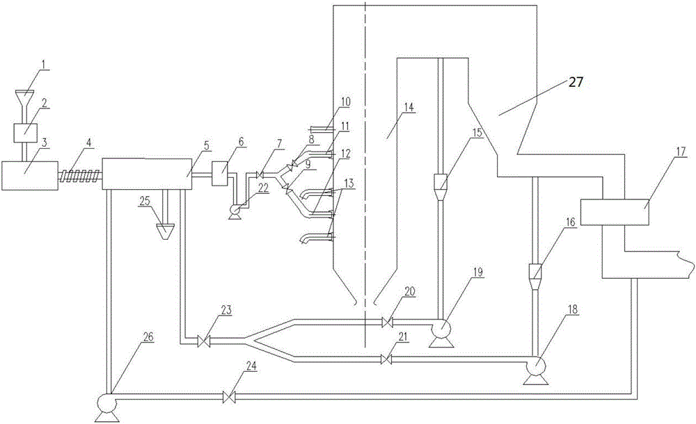
[0016] figure 1 It is a block diagram of the solid waste pyrolysis and combustion system, a solid waste pyrolysis and combustion system, including a feed bin 1, a crushing device 2, a dryer 3, a feeder 4, a pyrolysis furnace 5, and a pyrolysis gas purification device 6 and the boiler 14; the pyrolysis gas purification device 6 is first connected to the pyrolysis gas fan 22, and then connected to the pyrolysis gas burner of the boiler 14 after connecting the pyrolys...


PUM


Abstract

The invention discloses a solid waste pyrogenation and combustion system. The solid waste pyrogenation and combustion system is characterized in that a pyrolysis gas purifying device is firstly connected with a pyrolysis gas draught fan and then is connected with a pyrolysis gas combustor of a boiler after being connected with a pyrolysis gas valve; two stages of smoke recycling openings are formed in the boiler; the first stage of smoke recycling opening is formed before an economizer of a main outlet of the boiler and is connected with a first pyrolysis draught fan; the second stage of smoke recycling opening is formed behind the economizer and is connected with a second pyrolysis draught fan; the first pyrolysis draught fan passes through a first pyrolysis control valve and is then connected with a pyrolysis main control valve; and the second pyrolysis draught fan passes through a second pyrolysis control valve and is then connected with the pyrolysis main control valve. Combined utilization of solid waste pyrogenation and boiler combustion is achieved, solid waste pyrogenation can be used for achieving resource recycling, compared with incineration power generation, the pyrogenation technology is obvious in solid waste reduction effect, and meanwhile the problem of pollution of dioxin and toxic heavy metal such as mercury, lead and cadmium can be solved. The solid waste pyrogenation and combustion system can be applied to solid waste treatment and boiler combustion on the large scale in the industry.

Description

technical field [0001] The invention relates to garbage treatment equipment, in particular to a solid waste pyrolysis and combustion system. Background technique [0002] With the continuous acceleration of urban modernization, the discharge of primary solid waste is increasing day by day. Traditional solid waste treatment methods cause serious land and air pollution, which is difficult to meet the needs of sustainable development. Solid waste is a kind of renewable resource. If it can be effectively integrated and utilized, it can create huge economic benefits. At present, government departments are paying more and more attention to the recycling of solid waste resources. With the acceleration of urbanization and industrialization, the construction of solid waste treatment facilities in my country will increase significantly in the future. [0003] The pyrolysis method uses the thermal instability of organic matter in solid waste, heats and distills it under anaerobic or ...

Claims


Application Information

Patent Timeline
Patent Type & Authority Applications(China)
IPC IPC(8): F23G5/027F23G5/033F23G5/16F23G5/46F23J15/02
CPCF23G5/027F23G5/033F23G5/165F23G5/46F23G2201/302F23G2201/303F23G2201/80F23G2206/203F23J15/02F23J15/022F23J2215/20F23J2215/301Y02E20/12
Inventor 蔡兴飞文岳雄魏焕鹏王立
Owner 深圳市众源环境技术有限公司
Why Eureka
Try Eureka